Inst ToolsInst ToolsInst Tools
  • Courses
  • Automation
    • PLC
    • Control System
    • Safety System
    • Communication
    • Fire & Gas System
  • Instrumentation
    • Design
    • Pressure
    • Temperature
    • Flow
    • Level
    • Vibration
    • Analyzer
    • Control Valve
    • Switch
    • Calibration
    • Erection & Commissioning
  • Interview
    • Instrumentation
    • Electrical
    • Electronics
    • Practical
  • Q&A
    • Instrumentation
    • Control System
    • Electrical
    • Electronics
    • Analog Electronics
    • Digital Electronics
    • Power Electronics
    • Microprocessor
  • Request
Search
  • Books
  • Software
  • Projects
  • Process
  • Tools
  • Basics
  • Formula
  • Power Plant
  • Root Cause Analysis
  • Electrical Basics
  • Animation
  • Standards
  • 4-20 mA Course
  • Siemens PLC Course
Reading: What is Live Zero in 4-20 mA Current Loop?
Share
Font ResizerAa
Inst ToolsInst Tools
Font ResizerAa
  • Courses
  • Design
  • PLC
  • Interview
  • Control System
Search
  • Courses
  • Automation
    • PLC
    • Control System
    • Safety System
    • Communication
    • Fire & Gas System
  • Instrumentation
    • Design
    • Pressure
    • Temperature
    • Flow
    • Level
    • Vibration
    • Analyzer
    • Control Valve
    • Switch
    • Calibration
    • Erection & Commissioning
  • Interview
    • Instrumentation
    • Electrical
    • Electronics
    • Practical
  • Q&A
    • Instrumentation
    • Control System
    • Electrical
    • Electronics
    • Analog Electronics
    • Digital Electronics
    • Power Electronics
    • Microprocessor
  • Request
Follow US
All rights reserved. Reproduction in whole or in part without written permission is prohibited.
Inst Tools > Blog > Basics > What is Live Zero in 4-20 mA Current Loop?

What is Live Zero in 4-20 mA Current Loop?

Last updated: July 5, 2025 9:25 am
Editorial Staff
Basics PLC Tutorials
1 Comment
Share
3 Min Read
SHARE

The popular myth about 4-20 mA, debunked.

A lot of C&I practitioners (including me) has long believed that the establishment of 4 mA as the lower range of the widely used analog current is due to the fact that at fault condition, the electronic signal will always fall to 0 mA. Hence, the creation of the term “live zero.”

Live Zero in 4-20 mA Current Loop

What is Live Zero in 4-20 mA Signals? Explained

Yes, an electronic signal may really fall to zero at certain fault circumstances e.g. disconnection between the transmitter and analog card receiver, but it is also possible to rise at 20 mA or at certain locking intermediate value given the fact that a lot of electronic transmitters now are “smart” which means that they can have self-diagnostic capabilities, allowing them to be programmed to assume a worst case deviation value. Chances are it won’t be 0 mA given a certain goal of a process during fault detection.

The viable reason behind the use of this “live zero” has hardly anything to do with failure. A live zero provides a minimum current for the signal source which enables the device to be powered from the receiver.

A term which we may have heard of called “two-wire transmission” defines this scenario and it eliminates the requirement of another pair of conductors to serve as the power source of a transmitter.

Figure 1 shows a transmitter operating on a “dead-zero” range such as the legacy 0-10 mA standard. This requires the provision of power supply connections to the device so four conductor wires are required for each transmitter.
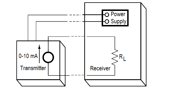
0 to 10 mA Current Loop

Figure 1: Without the “live zero” transmission

With a live zero, in Figure 2, the transmitter circuitry can already be powered from the receiver itself and only two conductor wires are required.
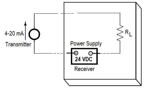
4 to 20 mA Current Loop

Figure 2: Two-wire transmission with “live zero”

Author: Jeremiah Cayondong

Profile: Linkedin

If you liked this article, then please subscribe to our YouTube Channel for PLC and SCADA video tutorials.

You can also follow us on Facebook and Twitter to receive daily updates.

Read Next:

  • 4-20mA Transmitter Signals
  •  3-15 psi, 10-15 mA, and 4-20 mA
  • Electronic Diagrams Schematics
  • Instrument Zero & Span Errors
  • HART Communicator Questions
Don't Miss Our Updates
Be the first to get exclusive content straight to your email.
We promise not to spam you. You can unsubscribe at any time.
Invalid email address
You've successfully subscribed !

Continue Reading

#3 PLC Best Practices – Leave Operational Logic in the PLC wherever feasible
Basics of Fail-safe Circuits
Safety Door Interlock PLC Program
PLC Program for Motor Starter
Check Block Consistency Tools in Simatic Manager
ON and OFF a Group of Outputs by One Push button PLC Logic
Share This Article
Facebook Whatsapp Whatsapp LinkedIn Copy Link
Share
1 Comment
  • Er Athar Sheikh says:
    March 11, 2022 at 9:55 pm

    Many instrumentation manufacturers produce 4–20 mA sensors which are loop powered The live or elevated zero of 4 mA allows powering of the device even with no process signal output from the field transmitter The accuracy of the signal is not affected by voltage drop in the interconnecting wiring.

    Reply

Leave a Reply Cancel reply

Your email address will not be published. Required fields are marked *

Stay Connected

128.3kFollowersLike
69.1kFollowersFollow
210kSubscribersSubscribe
38kFollowersFollow

Categories

Explore More

PLC Program using START and STOP Buttons
OFF Delay Timer using PLC
PLC Memory Mapping and I/O addressing
PLC Output Types
PLC Instruction List Program for Basic Instructions
Shutdown Motors in Timed Operation PLC Program
How to use JUMP Instruction in PLC Ladder Logic?
Electrical Earthing Calculations

Keep Learning

Ground Rod

What is a Ground Rod?

Pneumatic valve operation in sequence mode

Sequential PLC Programming for the Pneumatic Valves

Single Line Diagram of UPS System

UPS Selection Factors for a Control System

HMI Simulation for PID Controller

PID Controller Output Types – PID_PWM and PID_Output

Two Tanks Filling using PLC

PLC Ladder Logic for Tanks Filling as per Priority

Marking Machine

PLC SCL Program for Marking Machine

FactoryTalk View Studio Site Edition Pop-Up Confirm Action

How to Automatically Close Pop-up in FactoryTalk View Studio?

PLC Programming for Garden Sprinkle System

PLC Programming for Garden Sprinkler System

Learn More

How Does a Touch Sensor Work

How Does a Touch Sensor Work?

What is a Bourdon tube

Bourdon Tube Pressure Gauge Advantages and Disadvantages

Inability to Test Repaired HT Motors

Inability to Test Repaired HT Motors in Workshop Posed Problems

Top Electrical Engineering Interview Questions for Freshers

Top Electrical Engineering Interview Questions for Freshers

Formula of AMP, KW, KVA, HP for AC and DC Voltages

Formula of AMP, KW, KVA, HP for AC and DC Voltages

PLC Totalizer

PLC Program for Flow Totalizer

microwave flow detector applications

Microwave Flow Sensor – Working Principle and Applications

Bellows-Type Steam Trap

Bellows Steam Trap

Menu

  • About
  • Privacy Policy
  • Copyright

Quick Links

  • Learn PLC
  • Helping Hand
  • Part Time Job

YouTube Subscribe

Follow US
All rights reserved. Reproduction in whole or in part without written permission is prohibited.
Welcome Back!

Sign in to your account

Username or Email Address
Password

Lost your password?