Inst ToolsInst ToolsInst Tools
  • Ask
  • Courses
  • Videos
  • Q & A
    • Interview
      • Instrumentation
      • Electronics
      • Electrical
      • Practical Questions
    • MCQ
      • Instrumentation MCQ
      • Electrical MCQ
      • Electronics MCQ
      • Control Systems MCQ
      • Analog Electronics MCQ
      • Digital Electronics MCQ
      • Power Electronics MCQ
      • Microprocessor MCQ
      • Multiple Choice Questions
  • EE
    • Electronics
      • Electronics Q & A
      • Electronic Basics
      • Electronic Devices & Circuits
      • Electronics Animation
      • Digital Electronics
    • Electrical
      • Electrical Basics
      • Electrical Q & A
      • Power Electronics
      • Electrical Machines
      • Electrical Animation
      • Power Systems
      • Switchgear & Protection
      • Transmission & Distribution
  • Measure
    • Control Valves
    • Calibration
    • Temperature
    • Pressure
    • Flow
    • Level
    • Analyzers
    • Switches
    • Vibration
    • Solenoid Valve
  • Control
    • PLC Tutorials
    • Control Systems
    • Safety Instrumented System (SIS)
    • Communication
    • Fire & Gas System
  • More
    • Design
    • Tools
    • Animation
    • Basics
    • Formulas
    • Standards
    • TextBooks
    • Common
    • Software
    • Excel Tools
    • Erection & Commissioning
    • Process Fundamentals
    • Videos
    • Books
Search
All rights reserved. Reproduction in whole or in part without written permission is prohibited.
Reading: Determine the Problems with Level Transmitter and Gauge
Share
Notification Show More
Font ResizerAa
Inst ToolsInst Tools
Font ResizerAa
  • Courses
  • PLC Tutorials
  • Control Systems
Search
  • Ask
  • Courses
  • Videos
  • Q & A
    • Interview
    • MCQ
  • EE
    • Electronics
    • Electrical
  • Measure
    • Control Valves
    • Calibration
    • Temperature
    • Pressure
    • Flow
    • Level
    • Analyzers
    • Switches
    • Vibration
    • Solenoid Valve
  • Control
    • PLC Tutorials
    • Control Systems
    • Safety Instrumented System (SIS)
    • Communication
    • Fire & Gas System
  • More
    • Design
    • Tools
    • Animation
    • Basics
    • Formulas
    • Standards
    • TextBooks
    • Common
    • Software
    • Excel Tools
    • Erection & Commissioning
    • Process Fundamentals
    • Videos
    • Books
Follow US
All rights reserved. Reproduction in whole or in part without written permission is prohibited.
Inst Tools > Blog > Practical Questions > Determine the Problems with Level Transmitter and Gauge

Determine the Problems with Level Transmitter and Gauge

The level transmitter and level gauge indicates different readings. Determine the problems and find out the correct measurement.

Last updated: December 14, 2020 10:14 pm
Editorial Staff
Practical Questions
No Comments
Share
2 Min Read
SHARE

In this biogas generation system, cow manure is used as a feedstock to produce methane gas (CH4), which is then used to fuel an engine to turn a generator and make electricity.

The waste heat from the engine is used to maintain the cascaded digesters (“reactors” R-101 and R-102) at optimal temperatures for anaerobic bacteria to digest the manure and produce biogas (approximately 105oF):

Level Transmitter and Gauge

Determine the Problems with the Level Transmitter and Gauge

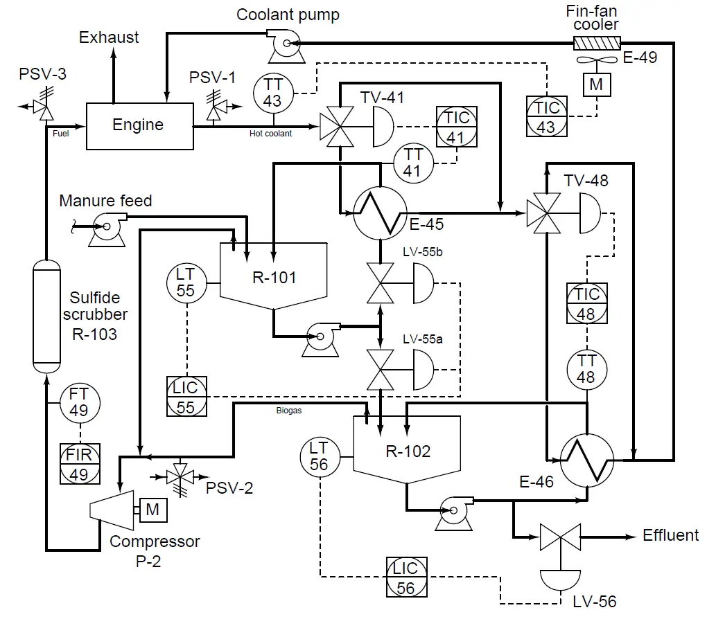
LIC-56 registers a manure level of 3 feet 10 inches, while the operator’s manual gauge reading is only 3 feet 7 inches. The calibrated range of LT-56 is 0 to 4 feet. Your first step is to measure current in the cable connecting LT-56 and LIC-56, and there your digital multimeter (DMM) registers 19.33 mA.

Based on this information, determine at least two potential problems in this system. Also, determine whether or not a hydrostatic (DP) level transmitter would be suitable for measuring manure level in R-102.

Answer:

The current value agrees with the indication at LIC-56, and so the problem is not with LIC-56. This leaves the transmitter (mis-calibrated, plugged impulse line), a change in process density (assuming a hydrostatic DP transmitter) or the operator’s manual measurement of manure level.

Hydrostatic (DP-based) level measurement is appropriate for R-102, assuming either remote seal(s) or purging. Otherwise, solids in the manure will surely plug up the transmitter’s impulse line(s) over time.

Share your answers with us through below comments section.

Read Next:

  • Instrument Hook Up Diagram
  • Instrumentation and Control MCQ
  • Pressure Gauge Datasheet
  • Temperature Controller Problem
  • Pressure Measurement MCQ

Credits: Tony R. Kuphaldt

Don't Miss Our Updates
Be the first to get exclusive content straight to your email.
We promise not to spam you. You can unsubscribe at any time.
Invalid email address
You've successfully subscribed !
Purpose of Stop in a Pressure Measuring Instrument
Programmable Logic Controller (PLC) Questions and Answers – 7
Compressor Emergency Shutdown Root Cause Analysis
Calculate Total Hydrostatic Pressure at Bottom of Vessel
How to Draw a Schematic Diagram ?
Share This Article
Facebook Whatsapp Whatsapp LinkedIn Copy Link
Share
Leave a Comment

Leave a Reply Cancel reply

Your email address will not be published. Required fields are marked *

Stay Connected

128.3kFollowersLike
69.1kFollowersFollow
208kSubscribersSubscribe
38kFollowersFollow

Categories

Recent Comments

  • Kamli on Top Free PLC Software
  • Guifty Shimica on Top Non-PLC Certification Courses for Automation Professionals
  • Guifty Shimica on Top Non-PLC Certification Courses for Automation Professionals
  • MIHARITSOA Aina Sitraka on Top Non-PLC Certification Courses for Automation Professionals

Related Articles

Loop Diagram

PT Loop Diagram Faults

DP transmitter Errors

DP Transmitter Calibration Errors

Is it Possible to Measure liquid-liquid Level Interface using Float

Is it Possible to Measure Liquid-Liquid Level Interface using Float?

Problem on Solar Hot Air Collector and Variable Speed Fan

Problem on Solar Hot Air Collector and Variable Speed Fan

simulate a thermocouple

Calculate the appropriate millivoltage values of a Thermocouple

level control system

Practical Process Control System Questions & Answers – 11

Foxboro pneumatic instruments

Pneumatic Force Balance Instrument

Float-type Level Switch for Sensing Low Oil Level

Float-type Level Switch for Sensing Low Oil Level

More Articles

Bubbler Level Measurement Animation

Bubbler Level Measurement Animation

Search tank in Intouch Scada

Tank Filling and Emptying using Intouch Scada Script

Parallel Circuit Unknown Resistance

Simplified Formulas for Parallel Circuit Resistance Calculations

Power Systems Questions & Answers

Power Systems MCQ Series 19

CO2 Analzer Working Principle

Infrared Non Dispersive CO2 Analyzer Working Principle

Difference Between Adhesion and Cohesion

Difference Between Adhesion and Cohesion

Optical Torsion Meter Principle

Optical Torsion Meter Principle

Mathematical Models of Physical Systems

Transfer Functions Objective Questions

Follow US
All rights reserved. Reproduction in whole or in part without written permission is prohibited.
Welcome Back!

Sign in to your account

Username or Email Address
Password

Lost your password?