Inst ToolsInst ToolsInst Tools
  • Courses
  • Automation
    • PLC
    • Control System
    • Safety System
    • Communication
    • Fire & Gas System
  • Instrumentation
    • Design
    • Pressure
    • Temperature
    • Flow
    • Level
    • Vibration
    • Analyzer
    • Control Valve
    • Switch
    • Calibration
    • Erection & Commissioning
  • Interview
    • Instrumentation
    • Electrical
    • Electronics
    • Practical
  • Q&A
    • Instrumentation
    • Control System
    • Electrical
    • Electronics
    • Analog Electronics
    • Digital Electronics
    • Power Electronics
    • Microprocessor
  • Request
Search
  • Books
  • Software
  • Projects
  • Process
  • Tools
  • Basics
  • Formula
  • Power Plant
  • Root Cause Analysis
  • Electrical Basics
  • Animation
  • Standards
  • 4-20 mA Course
  • Siemens PLC Course
Reading: Level Calculation with Remote Seals
Share
Font ResizerAa
Inst ToolsInst Tools
Font ResizerAa
  • Courses
  • Design
  • PLC
  • Interview
  • Control System
Search
  • Courses
  • Automation
    • PLC
    • Control System
    • Safety System
    • Communication
    • Fire & Gas System
  • Instrumentation
    • Design
    • Pressure
    • Temperature
    • Flow
    • Level
    • Vibration
    • Analyzer
    • Control Valve
    • Switch
    • Calibration
    • Erection & Commissioning
  • Interview
    • Instrumentation
    • Electrical
    • Electronics
    • Practical
  • Q&A
    • Instrumentation
    • Control System
    • Electrical
    • Electronics
    • Analog Electronics
    • Digital Electronics
    • Power Electronics
    • Microprocessor
  • Request
Follow US
All rights reserved. Reproduction in whole or in part without written permission is prohibited.
Inst Tools > Blog > Formulas > Level Calculation with Remote Seals

Level Calculation with Remote Seals

Last updated: April 19, 2019 5:48 pm
Editorial Staff
Formulas Level Measurement
2 Comments
Share
2 Min Read
SHARE

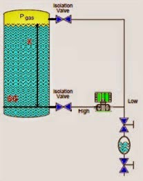
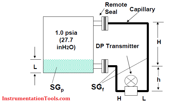
Diaphragm seals for tanks under Vacuum

The transmitter must be mounted level with or below the lowest tap to ensure positive pressure at the transmitter.

Contents
Diaphragm seals for tanks under VacuumDouble Remote Seal ApplicationDensity Calculation with Remote Seals TransmitterInterface Calculation with Remote Seals Transmitter

Level Calculation with Remote Seals

Dist. Between Taps = H

DP = Hside – Lside

DP = (L*SGp + h*SGf ) – (H+h)*SGf

DP = L*SGp – H*SGf

Double Remote Seal Application

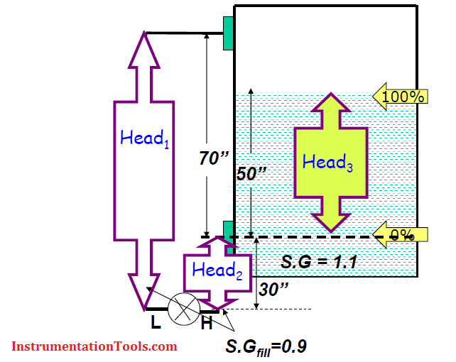
Double Remote Seal Application to Measure Level

Calibration Range

LRV or 4mA point = Phigh – Plow
LRV = Head2 – Head1

LRV = (0.9*30”) – (0.9*100”)

LRV = -63”H2O

URV or 20mA Point = Phigh – Plow
URV = (Head2 + Head3) – Head1

URV = [(0.9*30”) + (1.1*50”)] – (0.9*100”)

URV = -8”H2O

Cal. Range = -63 to -8 in H2O

Density Calculation with Remote Seals Transmitter

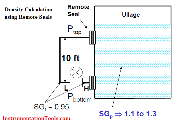
Density Calculation with Remote Seals Transmitter

Max. Allowable ΔS.G = 0.2

Dist. Betw. Taps = 10 ft = 10 x 12” = 120”

Calibration Range

LRV or 4mA point = 120” * (SGp – SGf)

LRV = 120” * (1.1 – 0.95)

LRV = 18”H2O

URV or 20mA Point = 120” * (SGp – SGf)

URV = 120” * (1.3 – 0.95)

URV = 42”H2O

Cal. Range = 18 to 42 inH2O

Interface Calculation with Remote Seals Transmitter

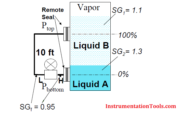
Application Example: To determine % of interface of Liquid A with respect to Liquid B.

Interface Calculation with Remote Seals

Dist. Betw. Taps = 10 ft = 10 x 12” = 120”

Calibration Range

LRV or 4mA point = 120” * (SG1 – SGf)

LRV = 120” * (1.1 – 0.95)

LRV = 18”H2O

URV or 20mA Point = 120” * (SG2 – SGf)

URV = 120” * (1.3 – 0.95)

URV = 42”H2O

Cal. Range = 18 to 42 inH2O

Also Read: Level Switch Animation
Don't Miss Our Updates
Be the first to get exclusive content straight to your email.
We promise not to spam you. You can unsubscribe at any time.
Invalid email address
You've successfully subscribed !

Continue Reading

Tank Level Detection Switches
Open Tank Level Measurement using DP Transmitters Animation
Magnetic Level Indicator Principle, Limitations, Installation and Calibration
Overview of Tank Gauging Technologies
Float Level Measurement
Point Level Detection Working Principle
Share This Article
Facebook Whatsapp Whatsapp LinkedIn Copy Link
Share
2 Comments
  • Karuna says:
    May 6, 2016 at 1:38 am

    Thanks for sharing the Remote Seals Level Calibration Procedure

    Reply
  • tad says:
    July 27, 2016 at 8:46 am

    wow this is fantastic

    Reply

Leave a Reply Cancel reply

Your email address will not be published. Required fields are marked *

Stay Connected

128.3kFollowersLike
69.1kFollowersFollow
210kSubscribersSubscribe
38kFollowersFollow

Categories

Explore More

DP Transmitter with Two Seals applications
Basics of Sight Glass Level Gauge
Guided Wave Radar Questions and Answers
Level Instruments Design Rules
Level Transmitter Animation
Level Gauges Objective Questions and Answers – Instrumentation
Calculate Process Variable from Transmitter Current
Hybrid Level Measurement Principle, Selection, Installation, Limitations and Calibration

Keep Learning

Guided-wave Radar Level Measurement Animation

Why Measure Level

4-20mA VFD Drive Formula

4-20mA Linear Conversion Calculation for VFD Drive (Formula)

Closed-tank-DP-Level-Transmitter-with-cleaning-leg-Calibration

Closed tank DP Level Transmitter with cleaning leg Calibration

remote seal capillary type dp transmitter

Closed Tank Remote Seal Capillary type DP Transmitter

How is pressure drop calculated through a valve?

How is Pressure Drop Calculated through a Valve ?

Stilling well in liquid level measurement

Stilling Well in Interface Level Measurement System

electromechanical-level-measurement-working-principle

ElectroMechanical Level Measurement Working Principle

Learn More

International Standards - Types and their Details

International Standards – Types and Their Details

Gas-detection-system

Selection Criteria for Toxic Gas Detector

Current Earth Leakage Circuit Breaker

Types of Earth Leakage Circuit Breaker

Free Mitsubishi PLC Online Training Courses

Free Mitsubishi PLC Online Training Course and Tutorials

PLC Motor Control Ladder Logic

PLC Program for Star Delta Motor Starter

PRV

Direct-actuated Safety and Relief Valves

What is Energy Monitoring System

What is Energy Monitoring System ?

PLC Program for Tank Heating Control using Heater

PLC Programming for Tank Heating Control using Heater

Menu

  • About
  • Privacy Policy
  • Copyright

Quick Links

  • Learn PLC
  • Helping Hand
  • Part Time Job

YouTube Subscribe

Follow US
All rights reserved. Reproduction in whole or in part without written permission is prohibited.
Welcome Back!

Sign in to your account

Username or Email Address
Password

Lost your password?