Inst ToolsInst ToolsInst Tools
  • Courses
  • Automation
    • PLC
    • Control System
    • Safety System
    • Communication
    • Fire & Gas System
  • Instrumentation
    • Design
    • Pressure
    • Temperature
    • Flow
    • Level
    • Vibration
    • Analyzer
    • Control Valve
    • Switch
    • Calibration
    • Erection & Commissioning
  • Interview
    • Instrumentation
    • Electrical
    • Electronics
    • Practical
  • Q&A
    • Instrumentation
    • Control System
    • Electrical
    • Electronics
    • Analog Electronics
    • Digital Electronics
    • Power Electronics
    • Microprocessor
  • Request
Search
  • Books
  • Software
  • Projects
  • Process
  • Tools
  • Basics
  • Formula
  • Power Plant
  • Root Cause Analysis
  • Electrical Basics
  • Animation
  • Standards
  • 4-20 mA Course
  • Siemens PLC Course
Reading: Lamp Control using PLC Logic Condition
Share
Font ResizerAa
Inst ToolsInst Tools
Font ResizerAa
  • Courses
  • Design
  • PLC
  • Interview
  • Control System
Search
  • Courses
  • Automation
    • PLC
    • Control System
    • Safety System
    • Communication
    • Fire & Gas System
  • Instrumentation
    • Design
    • Pressure
    • Temperature
    • Flow
    • Level
    • Vibration
    • Analyzer
    • Control Valve
    • Switch
    • Calibration
    • Erection & Commissioning
  • Interview
    • Instrumentation
    • Electrical
    • Electronics
    • Practical
  • Q&A
    • Instrumentation
    • Control System
    • Electrical
    • Electronics
    • Analog Electronics
    • Digital Electronics
    • Power Electronics
    • Microprocessor
  • Request
Follow US
All rights reserved. Reproduction in whole or in part without written permission is prohibited.
Inst Tools > Blog > PLC Tutorials > Lamp Control using PLC Logic Condition

Lamp Control using PLC Logic Condition

Last updated: March 4, 2021 3:44 pm
Editorial Staff
PLC Tutorials
2 Comments
Share
3 Min Read
SHARE

Build the ladder logic program to turn ON and OFF the lamp using push buttons with respect to program logic conditions.

Contents
PLC Lamp ControlPLC Problem LogicList of Inputs and OutputsPLC Lamp ProgramPLC Lamp Ladder Logic DescriptionConclusion:

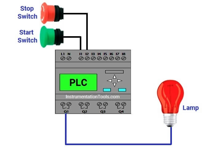
PLC Lamp Control

PLC Lamp Control using Logic Condition

PLC Problem Logic

Start PB and Stop PB are used to turn ON and OFF the lamp.

It should follow the following two cases.

CASE 1 :

Start PB is used to turn ON the lamp, Same Start PB is thrown again to turn OFF the lamp.

CASE 2 :

Start PB is Pressed to turn on the Lamp, if stop PB is pressed to turn OFF the lamp, Start PB is pressed twice to turn ON the lamp again.
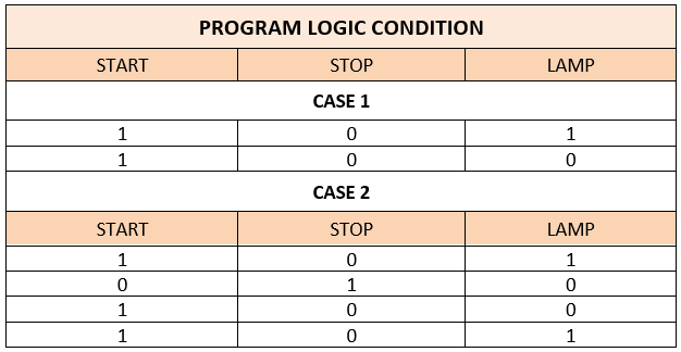
PLC Lamp Logic Condition

NOTE: Both the cases should satisfy in single program using minimum number of memories. Its user choice to pick the case option.

List of Inputs and Outputs
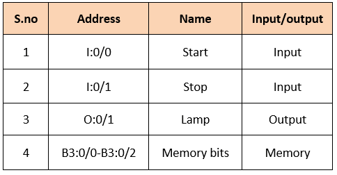
PLC Lamp Logic Inputs and Outputs

PLC Lamp Program

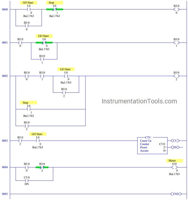
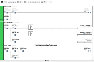
PLC Lamp Ladder Logic using Logic Condition

PLC Lamp Ladder Logic Description

RUNG 0000

Latching rung to operate the system through Master Start and Stop PB.

RUNG 0001

To store the status of start PB (When we released hand after we pressed it for first time) when lamp is in ON condition. Since we are using Push Buttons, Memory Switch B3:0/1 is connected in parallel.

RUNG 0002

To store the status of Start PB ON condition for second time to turn off the lamp (Refer CASE 1 in program logic).

Stop PB is connected in parallel as normally open PB to perform OFF condition of lamp.(Refer CASE 2 in program logic).

Since we are using Push Buttons, Memory Switch B3:0/2 is connected in parallel (Latching).

RUNG 0003

For CASE 2 condition, when lamp is turned off using stop PB, Start PB is pressed twice to turn on Lamp .Counter is used to count the ON condition of start PB.

Rung 0004

Main rung to connect the Previous rung condition in series and parallel to turn ON/OFF lamp according to program logic.

Note: Memory bits are used to store the status and get the sequence of operation.

Conclusion:

The above explained ladder logic for lamp turn ON/OFF is for example only. We can use this example program to understand the working of Push Buttons, memory bit and latching in AB PLC.

Author : Hema Sundaresan

If you liked this article, then please subscribe to our YouTube Channel for PLC and SCADA video tutorials.

You can also follow us on Facebook and Twitter to receive daily updates.

Read Next:

Diode Protection Modules ?

PLC Important Questions

Automatic Control using PLC

PLC Drilling Machine Logic

Metro Project using PLC Program
Don't Miss Our Updates
Be the first to get exclusive content straight to your email.
We promise not to spam you. You can unsubscribe at any time.
Invalid email address
You've successfully subscribed !

Continue Reading

OMRON PLC Tutorial: Car Parking System Application
What is a Control Panel and its types?
Network Switch Port Allocation Details
PLC Application for Stamping Operation – Example Programming
PLC Basics – Manual Control, Closed Loop, ON-OFF with Hysteresis
Automatic Door Operation PLC Programming and Simulation
Share This Article
Facebook Whatsapp Whatsapp LinkedIn Copy Link
Share
2 Comments
  • Steve Wurgler says:
    June 18, 2020 at 9:01 pm

    Do you have to reset the counter?

    Reply
  • Naveen says:
    July 26, 2021 at 10:23 am

    In 4th rung why did you used motor.?

    Reply

Leave a Reply Cancel reply

Your email address will not be published. Required fields are marked *

Stay Connected

128.3kFollowersLike
69.1kFollowersFollow
210kSubscribersSubscribe
38kFollowersFollow

Categories

Explore More

PLC Timer Application in Security Camera Recording
Motor Starter Logic using Siemens PLC Tia Portal
Moving Data between PLCs – Siemens Basics – TSEND TRCV
Studio 5000: Programming Three Motors with Fixed Priorities
Allen Bradley PLC Interview Questions and Answers
Coil Type Timers in Siemens PLC Programming
Jog Function in Motor Start Stop Logic using PLC
Electrical Ladder Diagram Control using Timers Example

Keep Learning

Online time of the PLC

System and Local Time in PLC

Motor Library in Studio 5000 PLC

Create User-Defined Data Types and Function Blocks in Studio 5000

DCS Marshalling Cabinet Checks

PLC, DCS, and ESD Marshalling Cabinet Checks

PLC Instruction List Code

PLC Instruction List Program for Basic Instructions

PLC Logic for Stairway Lighting

Smart Automation Solutions: PLC Logic for Stairway Lighting

PLC Programming Example for a Batch Process

PLC Programming Example for a Batch Process

Online PLC Ladder Logic

Mis-conceptions of PLC Ladder Logic

Basic PLC Exercise on Heater and Cooler for Students

Basic PLC Exercise on Heater and Cooler for Students

Learn More

PLC Program for Fishpond Water Level Monitoring System

PLC Program for Artificial Fishpond Water Level Monitoring System

Digital Electronics Multiple Choice Questions

Hardware Description Language Objective Questions

Instrumentation Earthing

Instrumentation Earthing

Digital Electronics Multiple Choice Questions

Asynchronous Down Counter Objective Questions

Digital Electronics Multiple Choice Questions

Half Subtractor and Full Subtractor Objective Questions

Ultrasonic Level Switch Principle

Ultrasonic Level Switch Principle

Heavy Equipment Transport

4 Tips For Shipping Large Construction Equipment

Car Parking System PLC Program Example

Schneider Electric: Car Parking System with Calculations in PLC

Menu

  • About
  • Privacy Policy
  • Copyright

Quick Links

  • Learn PLC
  • Helping Hand
  • Part Time Job

YouTube Subscribe

Follow US
All rights reserved. Reproduction in whole or in part without written permission is prohibited.
Welcome Back!

Sign in to your account

Username or Email Address
Password

Lost your password?