This is a PLC Ladder Logic to calculate the flow rate and also count the total flow or totalizer.
Flow Meter Totalizer

By using some math, bit and comparator functions, prepare a PLC program that can calculate the flow rate of gas and also count the total flow.

Problem Solution:
- To calculate flow, first we have to measure differential pressure.
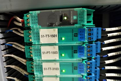
- To measure differential pressure, Differential Pressure transmitter installed at pipe line.
- Range of DP transmitter is 0-1000 Pa.
- Output of this transmitter is in standard electrical signal which is 4-20 mA. Convert this signal into digital signal by connecting transmitter to AI module of PLC.
- To find the Flow Rate, Apply formula ( Flow Rate = k √∆P ) given by the designer using math block in PLC.
- Prepare a logic for Flow totalizer using math function in PLC.
NOTE :
In this example, we are assuming the transmitter output 4-20 mA is equivalent to “Differential Pressure” instead of direct flow reading. So we are applying the square root function in PLC to derive the equivalent flow rate from this measured “differential pressure”.
PLC Address & Data Types

PLC Ladder Logic
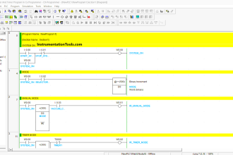
Network 1 :

In this Network 1, we are converting Analog Signal of the Differential Pressure Transmitter which is in 4 – 20 mA to digital value 0-1000 Pa.
Network 2 :

In the Network 2, We are finding Flow Rate by applying formula( Flow Rate = k √∆P ). Where k is the constant which is 10000 in my case and ∆P is the differential pressure in Pascal, which we are getting from the above network.
So we are using square root block and multiplication block to achieve this formula.
The unit of flow rate is m3/hr.
Network 3 :

Now this is tricky network, if you count the total flow then you must do increment the flow rate at every minimum time frame whichever is possible.
So here I have used clock memory here and minimum possibility of time frame of my PLC is 0.1s (seconds). So I have to find out the flow rate at 0.1s for that.
I have used the below formula to find out the flow rate at 0.1s

Network 4 :

In this Network 4, we are doing addition of flow rate at 0.1s at every 0.1s and save it to Total_Flow.
This is the totalizer of the flow.
If you liked this article, then please subscribe to our YouTube Channel for PLC and SCADA video tutorials.
You can also follow us on Facebook and Twitter to receive daily updates.
Read Next:


Hi,
How to find K constant?
Please give that formula
Hi Navaneethan, did you ever find out how to find the K formula, I am looking for it as well.
Hi,
How did you create pulses for every second?
Hi sir/maam
how to create the scaling program
Hello,
I would like to know how did you create the function call for the Analog to digital converter. Or it n embeded Function call from you PLC software…. Coz me I’m using Phoenix contact and trying to find the function converter.
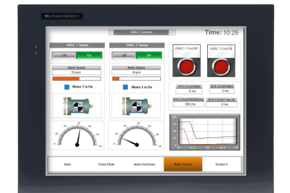
Good one. The output can also go to a data block ( BBD) if a display on HMI is required. This will help production in determining flowrate analysis of a process over a period. In decision making, the business will look at cost reduction if need be. As an engineer, When there is a need to optimize a process, I think safety; quality and cost reduction which eventually translates to Improved revenue.