Inst ToolsInst ToolsInst Tools
  • Courses
  • Videos
  • Q & A
    • Interview
      • Instrumentation
      • Electronics
      • Electrical
      • Practical Questions
    • MCQ
      • Instrumentation MCQ
      • Electrical MCQ
      • Electronics MCQ
      • Control Systems MCQ
      • Analog Electronics MCQ
      • Digital Electronics MCQ
      • Power Electronics MCQ
      • Microprocessor MCQ
      • Multiple Choice Questions
  • EE
    • Electronics
      • Electronics Q & A
      • Electronic Basics
      • Electronic Devices & Circuits
      • Electronics Animation
      • Digital Electronics
    • Electrical
      • Electrical Basics
      • Electrical Q & A
      • Power Electronics
      • Electrical Machines
      • Electrical Animation
      • Power Systems
      • Switchgear & Protection
      • Transmission & Distribution
  • Measure
    • Control Valves
    • Calibration
    • Temperature
    • Pressure
    • Flow
    • Level
    • Analyzers
    • Switches
    • Vibration
    • Solenoid Valve
  • Control
    • PLC Tutorials
    • Control Systems
    • Safety Instrumented System (SIS)
    • Communication
    • Fire & Gas System
  • More
    • Design
    • Tools
    • Animation
    • Basics
    • Formulas
    • Standards
    • TextBooks
    • Common
    • Software
    • Excel Tools
    • Erection & Commissioning
    • Process Fundamentals
    • Videos
    • Books
Search
All rights reserved. Reproduction in whole or in part without written permission is prohibited.
Reading: Ladder Logic for Flow Meter Totalizer
Share
Notification Show More
Font ResizerAa
Inst ToolsInst Tools
Font ResizerAa
  • Courses
  • PLC Tutorials
  • Control Systems
Search
  • Courses
  • Videos
  • Q & A
    • Interview
    • MCQ
  • EE
    • Electronics
    • Electrical
  • Measure
    • Control Valves
    • Calibration
    • Temperature
    • Pressure
    • Flow
    • Level
    • Analyzers
    • Switches
    • Vibration
    • Solenoid Valve
  • Control
    • PLC Tutorials
    • Control Systems
    • Safety Instrumented System (SIS)
    • Communication
    • Fire & Gas System
  • More
    • Design
    • Tools
    • Animation
    • Basics
    • Formulas
    • Standards
    • TextBooks
    • Common
    • Software
    • Excel Tools
    • Erection & Commissioning
    • Process Fundamentals
    • Videos
    • Books
Follow US
All rights reserved. Reproduction in whole or in part without written permission is prohibited.
Inst Tools > Blog > PLC Tutorials > Ladder Logic for Flow Meter Totalizer

Ladder Logic for Flow Meter Totalizer

Last updated: March 4, 2021 3:24 pm
Editorial Staff
PLC Tutorials
6 Comments
Share
3 Min Read
SHARE

This is a PLC Ladder Logic to calculate the flow rate and also count the total flow or totalizer.

Contents
Flow Meter TotalizerProblem Solution:NOTE :PLC Address & Data TypesPLC Ladder LogicNetwork 1 :Network 2 :Network 3 :Network 4 :

Flow Meter Totalizer

Ladder Logic for Flow Meter Totalizer

By using some math, bit and comparator functions, prepare a PLC program that can calculate the flow rate of gas and also count the total flow.
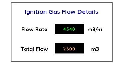
Flow Totalizer Graphics

Problem Solution:

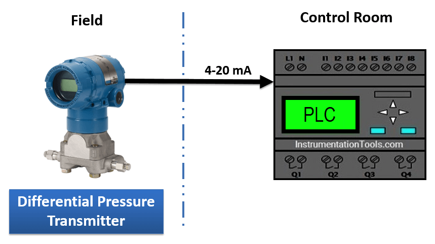
  • To calculate flow, first we have to measure differential pressure.
  • To measure differential pressure, Differential Pressure transmitter installed at pipe line.
  • Range of DP transmitter is 0-1000 Pa.
  • Output of this transmitter is in standard electrical signal which is 4-20 mA. Convert this signal into digital signal by connecting transmitter to AI module of PLC.
  • To find the Flow Rate, Apply formula ( Flow Rate = k √∆P ) given by the designer using math block in PLC.
  • Prepare a logic for Flow totalizer using math function in PLC.

NOTE :

In this example, we are assuming the transmitter output 4-20 mA is equivalent to “Differential Pressure” instead of direct flow reading. So we are applying the square root function in PLC to derive the equivalent flow rate from this measured “differential pressure”.

PLC Address & Data Types

Flow Totalizer Data Type

PLC Ladder Logic

Network 1 :

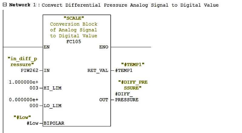
PLC Conversion Block from Analog Signal into Digital

In this Network 1, we are converting Analog Signal of the Differential Pressure Transmitter which is in 4 – 20 mA to digital value 0-1000 Pa.

Network 2 :
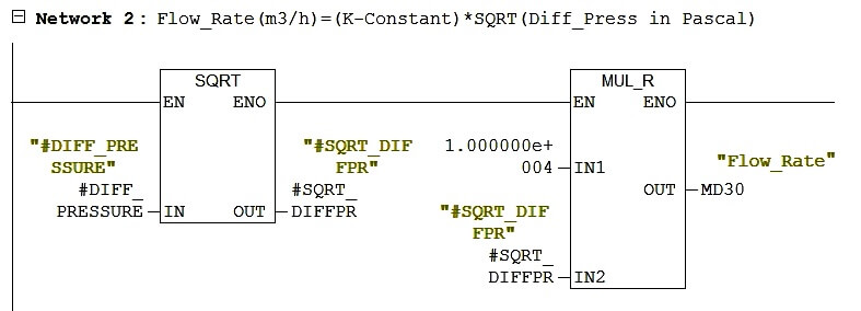
Flow Rate Formula in PLC

In the Network 2, We are finding Flow Rate by applying formula( Flow Rate = k √∆P ). Where k is the constant which is 10000 in my case and ∆P is the differential pressure in Pascal, which we are getting from the above network.

So we are using square root block and multiplication block to achieve this formula.

The unit of flow rate is m3/hr.

Network 3 :
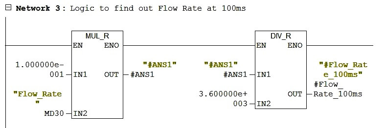
Ladder Logic to Find Flow Rate

Now this is tricky network, if you count the total flow then you must do increment the flow rate at every minimum time frame whichever is possible.

So here I have used clock memory here and minimum possibility of time frame of my PLC is 0.1s (seconds). So I have to find out the flow rate at 0.1s for that.

I have used the below formula to find out the flow rate at 0.1s

Flow Totalizer Formula

Network 4 :

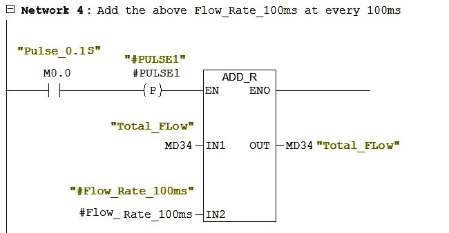
Ladder Logic for Total Flow

In this Network 4, we are doing addition of flow rate at 0.1s at every 0.1s and save it to Total_Flow.

This is the totalizer of the flow.

Author : Hiral Patel

If you liked this article, then please subscribe to our YouTube Channel for PLC and SCADA video tutorials.

You can also follow us on Facebook and Twitter to receive daily updates.

Read Next:
PLC Logic Example with Timers

Conveyor Ladder Logic Program

PLC Maintenance Check List

Draw Logic to control Buld

PLC Counters Programming

Don't Miss Our Updates
Be the first to get exclusive content straight to your email.
We promise not to spam you. You can unsubscribe at any time.
Invalid email address
You've successfully subscribed !

Recommended Articles

How to Create DFB in Schneider PLC? – Derived Function Block
Upgrading and Migration of PLC Systems
PLC SCL Program for Marking Machine
How to use Masked Move Instruction in PLC
Establishing a Modbus Driver for SCADA Indusoft Web Studio
DCS Commissioning Steps
Share This Article
Facebook Whatsapp Whatsapp LinkedIn Copy Link
Share
6 Comments
  • NAVANEETHAN VISWALINGAM says:
    May 6, 2020 at 9:33 am

    Hi,
    How to find K constant?
    Please give that formula

    Reply
  • Michael says:
    June 11, 2020 at 12:13 am

    Hi Navaneethan, did you ever find out how to find the K formula, I am looking for it as well.

    Reply
  • Durgesh Birhade says:
    October 19, 2020 at 4:03 pm

    Hi,
    How did you create pulses for every second?

    Reply
  • Gilbert De Vera says:
    January 27, 2021 at 11:56 am

    Hi sir/maam
    how to create the scaling program

    Reply
  • Patrick says:
    June 17, 2024 at 7:31 pm

    Hello,
    I would like to know how did you create the function call for the Analog to digital converter. Or it n embeded Function call from you PLC software…. Coz me I’m using Phoenix contact and trying to find the function converter.

    Reply
  • JOHNSON UZOMAH says:
    December 5, 2024 at 10:07 am

    Good one. The output can also go to a data block ( BBD) if a display on HMI is required. This will help production in determining flowrate analysis of a process over a period. In decision making, the business will look at cost reduction if need be. As an engineer, When there is a need to optimize a process, I think safety; quality and cost reduction which eventually translates to Improved revenue.

    Reply

Leave a Reply Cancel reply

Your email address will not be published. Required fields are marked *

Stay Connected

128.3kFollowersLike
69.1kFollowersFollow
208kSubscribersSubscribe
38kFollowersFollow

Categories

Recent Comments

  • William Snyder on Top Non-PLC Certification Courses for Automation Professionals
  • Kamli on Top Free PLC Software
  • Guifty Shimica on Top Non-PLC Certification Courses for Automation Professionals
  • Guifty Shimica on Top Non-PLC Certification Courses for Automation Professionals

Related Articles

Flip-Flop PLC Program for Lamps Application

Example of Flip-Flop PLC Program for Lamps Application

PLC Instruction List Code

PLC Instruction List Program for Basic Instructions

How CPU Execute Program in Siemens PLC?

How CPU Execute Program in Siemens PLC?

Best PLC for Your Project

Finding the Best PLC for Your Project – Tips and Tricks

What is the consumed tag in Studio 5000 software?

Produced Tags and Consumed Tags in Studio 5000

Energy Meter Data in PLC using Modbus Communication

Modbus Communication between PLC and Energy Meter

PLC programming for liquid mixing application code

PLC Mixing Logic in Liquids on EcoStruxure Machine Expert-Basic

Proper Earthing Practices Used for PLC Control Panel

Proper Earthing Practices Used for PLC Control Panel

More Articles

What is an Altitude Valve

What is an Altitude Valve?

Power Electronics Objective Questions

Single-Phase Full Wave AC-DC Converter Test

Current Divider Rule

Current Divider Rule

What is a Router

What is a Router? How Does a Router Work?

Discrete Manufacturing Automation

Discrete Manufacturing Automation

Ground Fault Versus Short Circuit

Difference Between Short Circuit and Ground Fault

SCADA Interview Questions

SCADA Interview Questions and Answers

Feedforward Control Questions & Answers

Feedforward Control Questions and Answers

Follow US
All rights reserved. Reproduction in whole or in part without written permission is prohibited.
Welcome Back!

Sign in to your account

Username or Email Address
Password

Lost your password?