This article explains the application of the Latching and Interlock concepts in PLC programming to control a pump using three different buttons with the TIA Portal software. In this system, the pump can only be activated by one button at a time. Each button is interconnected within the Interlock system, preventing the simultaneous operation of multiple buttons.
Program Objective
Step-by-step system:
Standby Mode: The system will be in standby condition when the START button is pressed, waiting for a command to activate the pump.
Pump Operation Buttons: There are three buttons to activate the pump, namely RUN-1, RUN-2, and RUN-3. Each button has a specific function to operate the pump.
Interlock and Latching Function: The system is designed with an interlock feature, which ensures that only one button (RUN-1, RUN-2, or RUN-3) can be active at a time.
The latching feature allows the pump to remain on even after the pressed button is released.
Alternating Operation: The RUN-1, RUN-2, and RUN-3 buttons can only be activated alternately. This means that if one button is already active, the others cannot be activated until the pump is turned off first.
Turning Off the Pump: The pump will only stop operating when the STOP button is pressed, and the system turns off.
Mapping Details
| S.No. | Comment | Input (I) | Output (Q) | Memory Bits |
|---|---|---|---|---|
| 1 | START | I0.0 | ||
| 2 | STOP | I0.1 | ||
| 3 | RUN_1 | I0.2 | ||
| 4 | RUN_2 | I0.3 | ||
| 5 | RUN_3 | I0.4 | ||
| 6 | PUMP | Q0.0 | ||
| 7 | LAMP_1 | Q0.1 | ||
| 8 | LAMP_2 | Q0.2 | ||
| 9 | LAMP_3 | Q0.3 | ||
| 10 | SYSTEM_ON | M0.0 |
Interlocking Three Inputs for Pump Logic
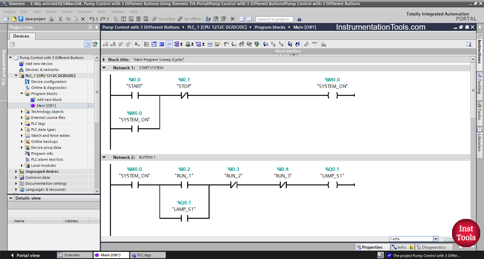
NETWORK 1 (START SYSTEM)
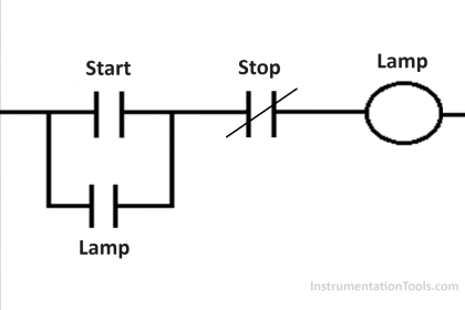
In this Network, the memory bit SYSTEM_ON (M0.0) will be in a HIGH state when the START (I0.0) button is pressed. The memory bit SYSTEM_ON (M0.0) remains in a HIGH state even though the START (I0.0) button has been released. Because it uses Latching.
The memory bit SYSTEM_ON (M0.0) will be in a LOW state if the STOP (I0.1) button is pressed.
NETWORK 2 (BUTTON 1)
The LAMP_1 (Q0.1) output changes to the ON state, when the NO contact of the memory bit SYSTEM_ON (M0.0) is in a HIGH state and the RUN_1 (I0.2) button is pressed.
Because it uses Latching, the LAMP_1 (Q0.1) output will remain ON even though the RUN_1 (I0.2) button has been released.
When the RUN_2 (I0.3) button or the RUN_3 (I0.4) button is pressed, the LAMP_1 (Q0.1) output will be OFF.
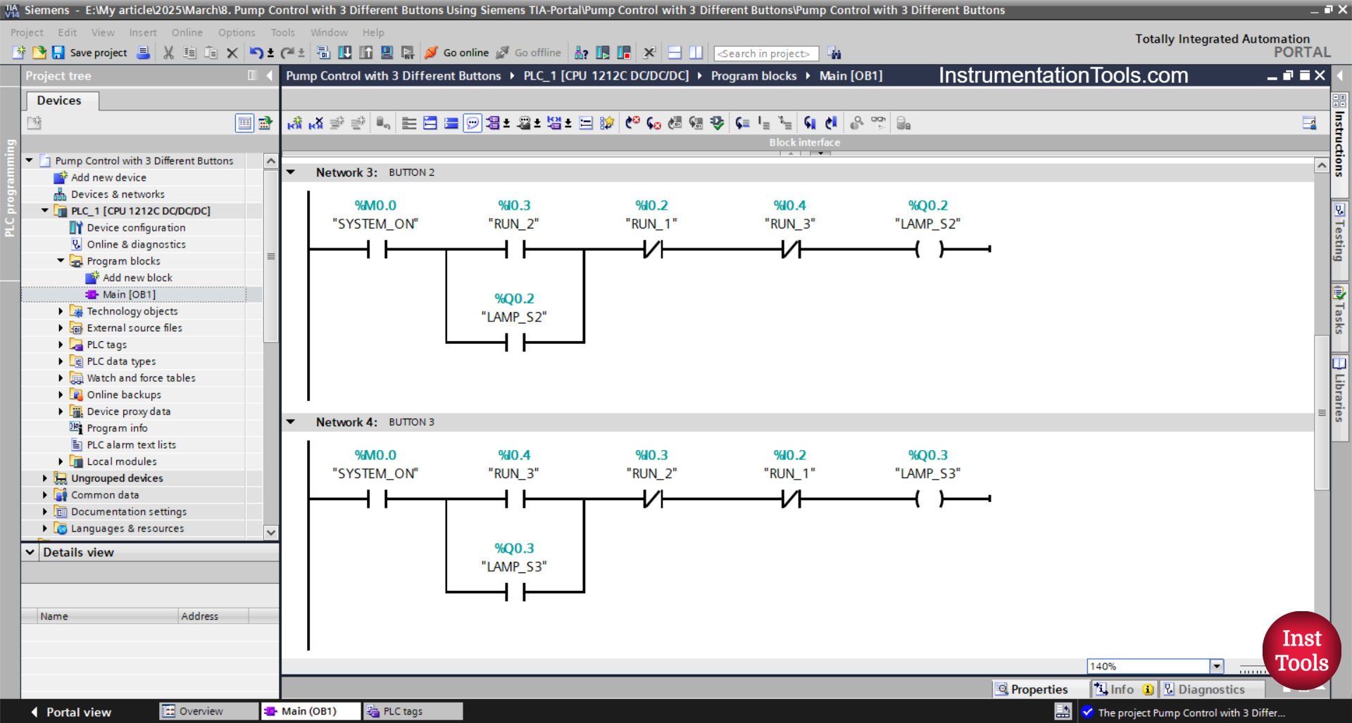
NETWORK 3 (BUTTON 2)
The LAMP_2 (Q0.2) output changes to the ON state when the NO contact of the memory bit SYSTEM_ON (M0.0) is in the HIGH state and the RUN_2(I0.3) button is pressed.
Because it uses Latching, the LAMP_2 (Q0.2) output will remain ON even though the RUN_2 (I0.3) button has been released.
The LAMP_2 (Q0.2) output will be OFF when the RUN_1 (I0.2) button or the RUN_3 (I0.4) button is pressed.
NETWORK 4 (BUTTON 3)
When the NO contact of the memory bit SYSTEM_ON (M0.0) is in the HIGH state and the RUN_3 (I0.4) button is pressed, the LAMP_3 (Q0.3) output changes to the ON state.
Because it uses Latching, the LAMP_3 (Q0.3) output will remain ON even though the RUN_3 (I0.4) button has been released.
The LAMP_3 (Q0.3) output will be OFF if the RUN_1 (I0.2) or RUN_2(I0.3) button is pressed.
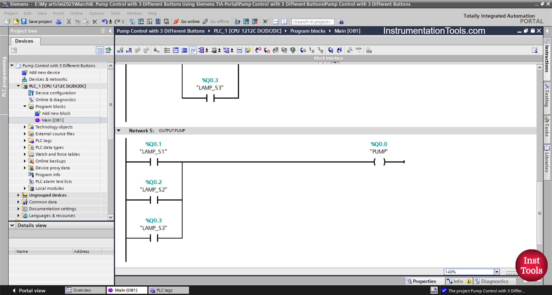
NETWORK 5 (OUTPUT PUMP)
In this network, the output PUMP (Q0.0) turns ON if any one of the NO contacts from LAMP_1 (Q0.1), LAMP_2 (Q0.2), or LAMP_3 (Q0.3) is in a HIGH state.
Read Next:
- Gas Monitoring Logic with Siemens PLC Programming
- Omron PLC Exercise to Sort Products by 10g, 15g, 20g
- Tia Portal Programming: Automatic Water Refill System
- PLC Control Sequence of Conveyors with Interlock
- Omron PLC Sample Code: Liquid Temperature Control Logic