This article provides an overview of an Insulation Resistance test and its Advantages, & Applications.
The insulation resistance test is not the most recent, but it is the most commonly used to determine the reliability of cables or windings within transformers, switchgear, motors, and electrical installations.
Insulation Resistance measurement is a common test performed on various types of cables and electrical wires.
This test is commonly used as a customer acceptance test, similar to a production test, with minimum insulation resistance for each unit length frequently specified by the customer.
The installation of the device, the type of usage, and the operating conditions are all factors that influence the IR test.
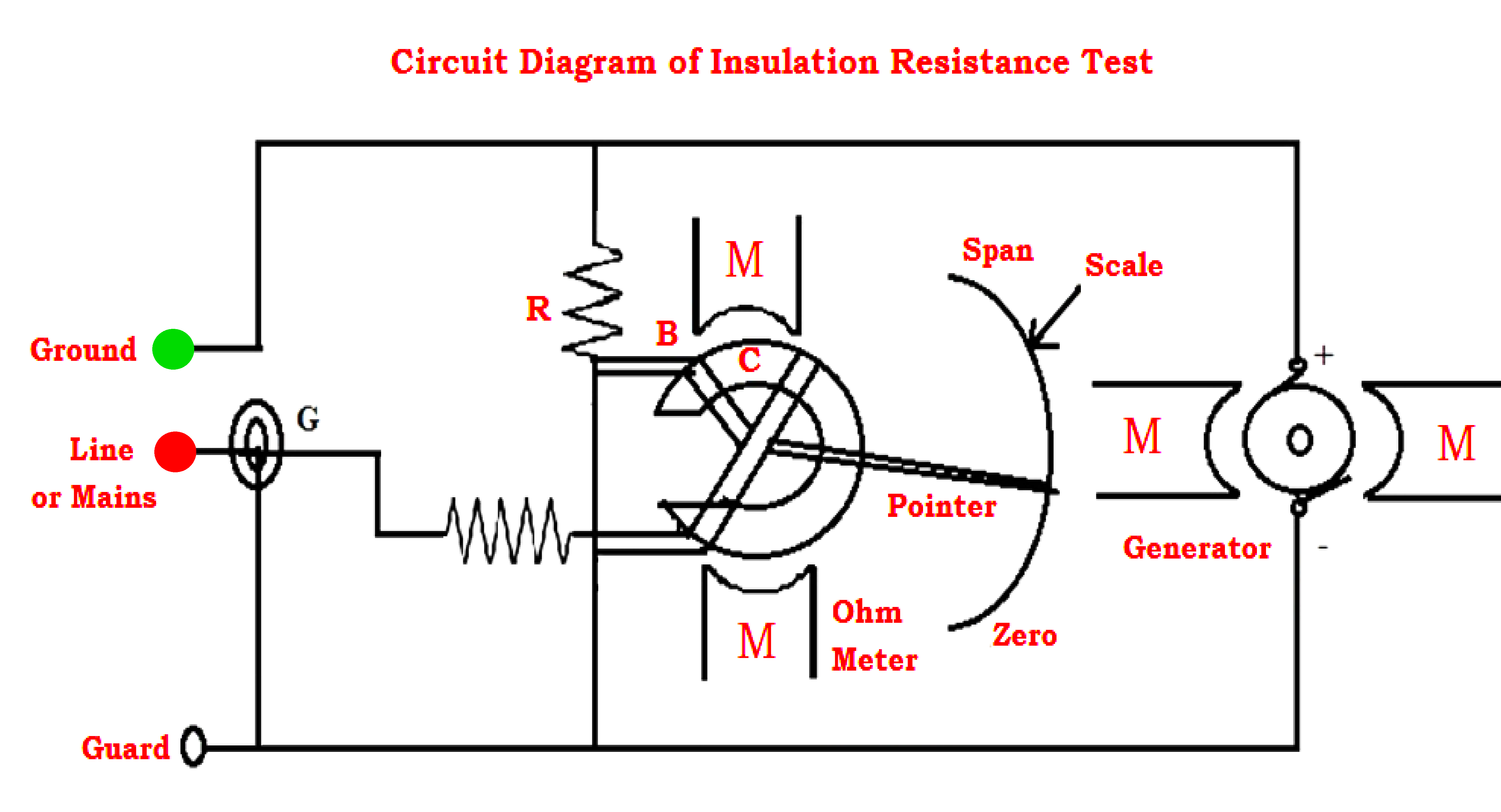
The insulation resistance test definition is the measurement of total resistance between any two points separated by electrical insulation. The megger test is another name for this test. As a result, this test is used to determine how effective the dielectric or insulation is at restricting the flow of electric current.
Insulation Resistance tests are very useful not only for verifying insulation quality when the product is manufactured, but also when the product is used over time.
The insulation resistance test principle is to measure the steady-state leakage current with a voltage and then divide the voltage by the current (R = V/I).
If the IR meets or beats the required value, the IR test is successful.
The target insulation resistance of the measurement can be calculated by measuring the flow of current to the target after the voltage ‘V’ is applied, and then dividing the applied voltage ‘V’ by the resulting current ‘I’.
Once an electric current is supplied through a conducting wire to its destination, there is a loss of electric current along the way for various reasons.
As a result, we must conduct insulation testing to determine whether or not there is any current leakage, as this leakage could be extremely dangerous.
This testing is critical for avoiding injury and damage.
As a result, this test should be performed to ensure the dependability of the electrical equipment.
By performing this test, we can determine if the electrical equipment is in good condition and approximate the service life of the insulation. Insulation testing should be performed while repairing new electrical equipment so that while testing electrical equipment, we can ensure that the insulation is in good working order.
Ohms Law can be used to calculate insulation resistance.
If we apply a voltage across a resistor, we can calculate the current flow using the formula R=V/I. This is a fundamental technique; we should be aware of various types of current such as capacitive charge, polarization, leakage, and conduction current.
An insulation resistance tester can be used to measure insulation resistance. This tester has three terminals, two of which are simply connected to a circuit to perform the test and the third to a guard terminal.
This terminal is used to select specific electrical components within large plant machinery.
The following procedure dissipates testing of insulation.
Before using the megger instrument, we must determine whether it provides an infinity value when not connected and a zero value when the two terminals are connected and the handle is turned.
To perform an insulation resistance test, make sure the cable is disconnected from any devices and that there is no eddy current within the device by grounding it.
Because resistance is proportional to temperature, the instrument must be at its normal operating temperature.
Check that both ends of the cable are separated from one another. Connect the megger’s two terminals to the conductors to be tested. If the reading is infinite, the conductor’s insulation is adequate.
This test is important because it determines the dependability of the insulation between conductors. This test aids in the detection of short circuits within the circuit.
Generally, we know that this Insulation Resistance Test is conducted by using a megger or mega-ohm meter.
Insulation Resistance Tests can be classified into three types as
The Short-Time or Spot-Reading test is as simple as connecting a Megger device across the insulation to be tested.
Following that, it is used for a short period, usually 60 seconds. It is critical to remember that humidity, temperature, and insulation conditions all have an impact on the reading.
The Time-Resistance testing method frequently yields conclusive results with no prior test results. This test is primarily dependent on good insulation absorption compared to contaminated insulation.
Throughout the insulation test, a device such as Megger will take straight readings at specific times and record the differences. If the insulation is good, this type of time resistance test should show a consistent increase in resistance over a set period.
Dielectric Absorption Ratio is the ratio of two time-resistance readings, and it is extremely useful for recording insulation data. A one-minute reading, for example, can be divided by 30 seconds of reading; thus, a Megger device will make this test easier and provide the best results.
So, while this device can run for one minute, it also allows you to take readings every 30 seconds and every minute.
PLC ladder logic design to control 3 motors with toggle switch and explain the program…
VFD simulator download: Master the online tool from the Yaskawa V1000 & programming software for…
The conveyor sorting machine is widely used in the packing industries using the PLC program…
Learn the example of flip-flop PLC program for lamps application using the ladder logic to…
In this article, you will learn the STAR DELTA programming using PLC controller to start…
Lube oil consoles of rotary equipment packages in industrial process plants are usually equipped with…

View Comments
What is the minimum value for the insulation resistance in a domestic electric installation?