Inst ToolsInst ToolsInst Tools
  • Courses
  • Automation
    • PLC
    • Control System
    • Safety System
    • Communication
    • Fire & Gas System
  • Instrumentation
    • Design
    • Pressure
    • Temperature
    • Flow
    • Level
    • Vibration
    • Analyzer
    • Control Valve
    • Switch
    • Calibration
    • Erection & Commissioning
  • Interview
    • Instrumentation
    • Electrical
    • Electronics
    • Practical
  • Q&A
    • Instrumentation
    • Control System
    • Electrical
    • Electronics
    • Analog Electronics
    • Digital Electronics
    • Power Electronics
    • Microprocessor
  • Request
Search
  • Books
  • Software
  • Projects
  • Process
  • Tools
  • Basics
  • Formula
  • Power Plant
  • Root Cause Analysis
  • Electrical Basics
  • Animation
  • Standards
  • 4-20 mA Course
  • Siemens PLC Course
Reading: Identify Instrumentation Terms in Water Supply System
Share
Font ResizerAa
Inst ToolsInst Tools
Font ResizerAa
  • Courses
  • Design
  • PLC
  • Interview
  • Control System
Search
  • Courses
  • Automation
    • PLC
    • Control System
    • Safety System
    • Communication
    • Fire & Gas System
  • Instrumentation
    • Design
    • Pressure
    • Temperature
    • Flow
    • Level
    • Vibration
    • Analyzer
    • Control Valve
    • Switch
    • Calibration
    • Erection & Commissioning
  • Interview
    • Instrumentation
    • Electrical
    • Electronics
    • Practical
  • Q&A
    • Instrumentation
    • Control System
    • Electrical
    • Electronics
    • Analog Electronics
    • Digital Electronics
    • Power Electronics
    • Microprocessor
  • Request
Follow US
All rights reserved. Reproduction in whole or in part without written permission is prohibited.
Inst Tools > Blog > Practical Questions > Identify Instrumentation Terms in Water Supply System

Identify Instrumentation Terms in Water Supply System

Last updated: January 6, 2020 10:26 am
Editorial Staff
Practical Questions
No Comments
Share
5 Min Read
SHARE

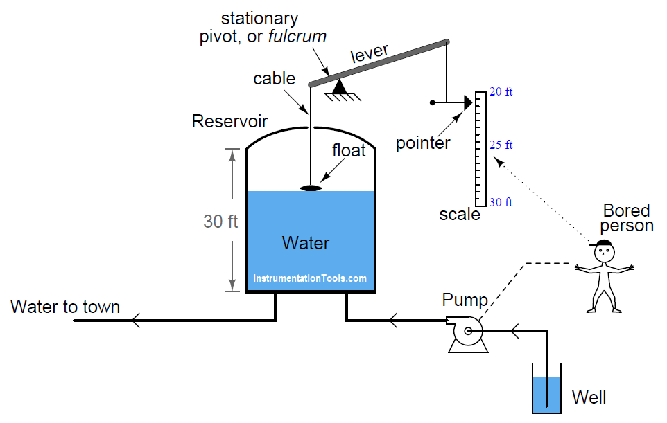
You have to Identify Instrumentation Terms in Water Supply System in this example problem. A water reservoir located high on a hill stores fresh water for a town’s drinking needs. A float connected to a lever provides visual indication of the water level inside the reservoir. Nearby this reservoir, a person has the most boring job in the world: to turn the pump on when the water level gets too low, and to turn the pump off when the water level gets too high.

Note that the float mechanism showing water level in the reservoir cannot show the entire capacity of the reservoir, but only the top ten feet (from 20 feet to 30 feet of level):

Identify Instrumentation Terms in Water Supply System

As crude as it is, this system contains instrumentation, and we may apply standard instrumentation terms to its components.

Apply the following terms to this water-supply system, as best as you can:

  • Process
  • Primary sensing element
  • Final control element
  • Measurement range
  • Lower-Range Value (LRV)
  • Upper-Range Value (URV)
  • Measurement span
  • Indicator
  • Transmitter
  • Controller
  • Measured Variable (or Process Variable)
  • Controlled Variable (or Manipulated Variable)

Solution:

  • Process: the water and all associated vessels, pipes, and pump
  • Primary sensing element: float
  • Final control element: pump
  • Measurement range: 20 ft to 30 ft
  • Lower-Range Value (LRV): 20 ft
  • Upper-Range Value (URV): 30 ft
  • Measurement span: 10 ft
  • Indicator: pointer and scale
  • Transmitter: lever, fulcrum, and cables
  • Controller: bored person
  • Measured Variable (or Process Variable): water level
  • Controlled Variable (or Manipulated Variable): pump speed (on/off status)

The distinction between measurement range, LRV, URV, and span is important. What we are measuring here is water level in the tank between the 20 and 30 foot marks. The difference in level between these marks is what we call the span. So in this case we have a span of 10 feet (30 feet − 20 feet). The LRV is the lower end of the measurement range: 20 feet. The URV is the upper end of the measurement range: 30 feet. The range of measurement encompasses both LRV and URV, and is stated “20 to 30 feet”.

By the same token, if you had a pressure transmitter in an air separation process ranged from 200 to 500 PSI, 200 PSI would be the LRV, 500 PSI would be the URV, and 300 PSI would be the span.

In any instrument system, the controller is the thing making control decisions. In this particular case, it would be the bored person. All the other hardware between the float and indicating pointer simply transmits information from the reservoir to that bored person (controller).

For the record, I really despise the term “controlled variable”. I find it misleading and confusing, but unfortunately it is often used when discussing process controls. While the “measured” or “process” variable is the thing we are measuring (and trying to hold to setpoint), the “controlled” or “manipulated” variable is the thing we are adjusting to effect the process variable. In this case, the process variable is the water level in the reservoir, and the controlled (or manipulated) variable is the pump speed. We are measuring water level, and controlling it by turning the pump on and off.

By analogy, imagine a cruise-control system in a car. The measured (process) variable there is car speed, while the accelerator pedal position is the controlled or manipulated variable, because pedal position is the variable adjusted by the cruise control system in order to maintain the car’s speed at setpoint.

Here are some generalized definitions:

  • Measured Variable (or Process Variable): The variable we are measuring, usually with intent to hold to a constant setpoint value
  • Controlled Variable (or Manipulated Variable): The variable directly manipulated by the controller, which effects the process variable

Crdits: Tony R. Kuphaldt

Read Next:

  • Distributed Control System Quiz
  • EPC Questions and Answers
  • RTD Testing Methods
  • How to Calibrate Load Cell?
  • Security of Automation System
Don't Miss Our Updates
Be the first to get exclusive content straight to your email.
We promise not to spam you. You can unsubscribe at any time.
Invalid email address
You've successfully subscribed !

Continue Reading

Calculate Amount of Weight Indicated by the Scale
Programmable Logic Controller (PLC) Questions and Answers – 13
Double Block and Bleed Valves Opening or Closing Sequence
Analyze the Relay Circuit and Find the Status ?
Problem with Pirani Gauge
Flow Transmitter Readings mismatch with DCS
Share This Article
Facebook Whatsapp Whatsapp LinkedIn Copy Link
Share
Leave a Comment

Leave a Reply Cancel reply

Your email address will not be published. Required fields are marked *

Stay Connected

128.3kFollowersLike
69.1kFollowersFollow
210kSubscribersSubscribe
38kFollowersFollow

Categories

Explore More

Problem on Tachogenerator
Calculate the Height of Glycerine
Three-valve Manifold on Remote Seal DP Transmitter
Pneumatic Relay Questions
Calculate the Magnitude of Hydrostatic Pressure
Air Pressure Regulator Questions
Problem on Solar Hot Air Collector and Variable Speed Fan
Determine Resistance value of Resistors

Keep Learning

Steam flow to the heat exchanger

Analytical Control System of Heat Exchanger Questions

Which Tube has most Hydrostatic Pressure

Which Tube has most Hydrostatic Pressure?

Loop Diagram

PT Loop Diagram Faults

Dip Tube Type Level System

Questions on Dip Tube Type Level System

displacer level transmitter cylindrical weighs

Displacer Level Transmitter 5-point Calibration

liquid flow control system

Practical Process Control System Questions & Answers – 7

Calculate Hydraulic System Fluid Pressure

Calculate Hydraulic System Fluid Pressure

Determine the Problems with the Level Transmitter and Gauge

Determine the Problems with Level Transmitter and Gauge

Learn More

PID Controller Types

PID Controllers : Parallel, Ideal & Series

Measurement and Instrumentation Objective Questions

Measurements & Instrumentation Quiz – Set 4

valve plug and seat damage

Control Valve Erosion Problems

What is Hot Standby in PLC

What is Hot Standby in PLC?

PLC Power Supply and Operating Voltages

PLC Power Supply and Operating Voltages

Fire-Triangle-in-Gas-Detection-System

Basics of Fire Detection System

Difference between Signal Cables and Control Cables

Difference between Signal Cables and Control Cables

Gas Turbine Troubleshooting Guide

Gas Turbine Troubleshooting Tips

Menu

  • About
  • Privacy Policy
  • Copyright

Quick Links

  • Learn PLC
  • Helping Hand
  • Part Time Job

YouTube Subscribe

Follow US
All rights reserved. Reproduction in whole or in part without written permission is prohibited.
Welcome Back!

Sign in to your account

Username or Email Address
Password

Lost your password?