Piping and Instrumentation Diagrams (P&IDs) use specific symbols to show the connectivity of equipment, sensors, and valves in a control system.
These symbols can represent actuators, sensors, and controllers and may be apparent in most, if not all, system diagrams.
P&IDs provide more detail than a process flow diagram with the exception of the parameters, i.e. temperature, pressure, and flow values. “Process equipment, valves, instruments and pipe lines are tagged with unique identification codes.
Piping and instrumentation diagrams, or P&IDs, are used to create important documentation for process industry facilities.
The shapes in this legend are representative of the functional relationship between piping, instrumentation, and system equipment units. We’ve broken them down into seven main groups: equipment, piping, vessels, heat exchangers, pumps, instruments, and valves.
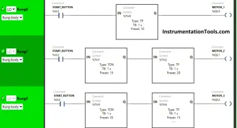
PLC ladder logic design to control 3 motors with toggle switch and explain the program…
VFD simulator download: Master the online tool from the Yaskawa V1000 & programming software for…
The conveyor sorting machine is widely used in the packing industries using the PLC program…
Learn the example of flip-flop PLC program for lamps application using the ladder logic to…
In this article, you will learn the STAR DELTA programming using PLC controller to start…
Lube oil consoles of rotary equipment packages in industrial process plants are usually equipped with…
View Comments
Great sources. No doubt, you're an authority in the industry.