Piping and Instrumentation Diagrams (P&IDs) use specific symbols to show the connectivity of equipment, sensors, and valves in a control system.
These symbols can represent actuators, sensors, and controllers and may be apparent in most, if not all, system diagrams.
P&IDs provide more detail than a process flow diagram with the exception of the parameters, i.e. temperature, pressure, and flow values. “Process equipment, valves, instruments and pipe lines are tagged with unique identification codes.
Piping and instrumentation diagrams, or P&IDs, are used to create important documentation for process industry facilities.
The shapes in this legend are representative of the functional relationship between piping, instrumentation, and system equipment units. We’ve broken them down into seven main groups: equipment, piping, vessels, heat exchangers, pumps, instruments, and valves.
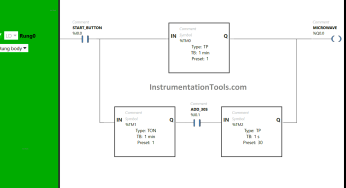
In this article, you will learn the PLC cooking timer example for kitchen automation using…
Learn an example PLC program to control a pump based on level sensors using ladder…
In the PLC timer application for security camera recording, when motion is detected then camera…
In this example, we will learn batch mixing with PLC ladder logic program using timer…
This PLC example on manufacturing line assembly is an intermediate-level PLC program prepared for the…
In this article, you will learn the PLC programming example with pushbutton and motor control…
View Comments
Great sources. No doubt, you're an authority in the industry.