Inst ToolsInst ToolsInst Tools
  • Courses
  • Automation
    • PLC
    • Control System
    • Safety System
    • Communication
    • Fire & Gas System
  • Instrumentation
    • Design
    • Pressure
    • Temperature
    • Flow
    • Level
    • Vibration
    • Analyzer
    • Control Valve
    • Switch
    • Calibration
    • Erection & Commissioning
  • Interview
    • Instrumentation
    • Electrical
    • Electronics
    • Practical
  • Q&A
    • Instrumentation
    • Control System
    • Electrical
    • Electronics
    • Analog Electronics
    • Digital Electronics
    • Power Electronics
    • Microprocessor
Search
  • Books
  • Software
  • Projects
  • Process
  • Tools
  • Basics
  • Formula
  • Power Plant
  • Root Cause Analysis
  • Electrical Basics
  • Animation
  • Standards
  • 4-20 mA Course
  • Siemens PLC Course
Reading: What is an Instrument Transformer? – Types, Principle, Advantages
Share
Notification Show More
Font ResizerAa
Inst ToolsInst Tools
Font ResizerAa
  • Courses
  • Design
  • PLC
  • Interview
  • Control System
Search
  • Courses
  • Automation
    • PLC
    • Control System
    • Safety System
    • Communication
    • Fire & Gas System
  • Instrumentation
    • Design
    • Pressure
    • Temperature
    • Flow
    • Level
    • Vibration
    • Analyzer
    • Control Valve
    • Switch
    • Calibration
    • Erection & Commissioning
  • Interview
    • Instrumentation
    • Electrical
    • Electronics
    • Practical
  • Q&A
    • Instrumentation
    • Control System
    • Electrical
    • Electronics
    • Analog Electronics
    • Digital Electronics
    • Power Electronics
    • Microprocessor
Follow US
All rights reserved. Reproduction in whole or in part without written permission is prohibited.
Inst Tools > Blog > Electrical Basics > What is an Instrument Transformer? – Types, Principle, Advantages

What is an Instrument Transformer? – Types, Principle, Advantages

In electrical engineering, a Current Transformers (CT) together with Potential Transformers (PT) is called an Instrument transformer.

Last updated: October 17, 2023 2:05 pm
R Jagan Mohan Rao
Electrical Basics
No Comments
Share
5 Min Read
SHARE

Instrument Transformers serve an important role in the protective systems that are used in AC systems for the measurement of various electrical parameters.

Contents
Instrument TransformerTypes of Instrument TransformersCurrent TransformerVoltage TransformerDos and Don’tsAdvantages of Instrument TransformerDisadvantages of Instrument Transformer

They are voltage, current, power, power factor, frequency, energy. As the name implies, these transformers are used in connection with suitable instruments such as ammeters, voltmeters, wattmeters, and energy meters. 

For the protection of power systems, Instrument transformers are also used with protective circuits to operate relays, circuit breakers, etc., the working of these transformers is similar to that of ordinary transformers. 

Instrument Transformer

The basic purpose of the Instrument transformer is to step down the alternating (ac) power system voltage and current and measure the respective signal.

The voltage and current levels of the power system are very high. It is very difficult and costly to design the measuring instruments for the measurement of such high-level voltage and current. Generally measuring instruments are designed for 5 amps and 110 Volts. 

The large amount of electrical parameters can be measured by using small rating measuring instrument transformers. Hence, these transformers are very popular in modern power systems. 

Types of Instrument Transformers

In electrical engineering, a Current Transformers (CT) together with Potential Transformers (PT) is called an Instrument transformer.

Current Transformer

A current transformer is used to step down the current of the power system to a lower level to make it possible to be measured by a small rating ammeter (5A).

A typical connection diagram of a current transformer is shown in the figure below. 

What is an Instrument Transformer?

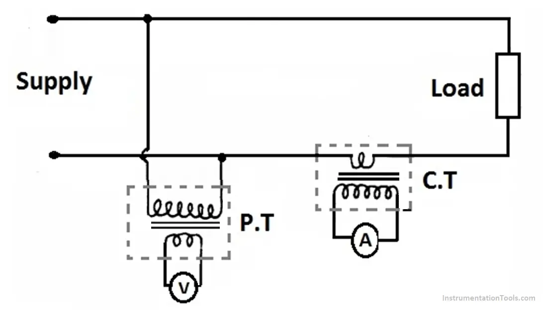
The primary winding of a current transformer (C.T) is connected in series with the load. The primary winding carries load current to be measured. 

The primary winding has very few turns while the secondary winding has more turns. Across the secondary winding, the ammeter is connected directly.

A current transformer may be considered as a series transformer, the primary winding of the current transformer should be connected in series of the circuit of whose current needs to be measured.  

Transformation Ratio of C.T = (Primary Winding Current / Secondary winding Current).

Turns Ratio for C.T = (Number of turns of secondary winding /Number of turns of primary winding).

For example, Turns ratio of CT is marked 600:5.

Voltage Transformer

These are used for the measurement of high voltages using low-range voltmeters. 

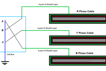
The primary winding of the voltage transformer is connected across a supply line (R, Y, and B) whose voltage is to be measured. Across the secondary winding, the voltage measuring circuit is connected. 

A voltage transformer is considered a parallel transformer, the primary voltage transformer should be connected in parallel to the circuit whose voltage needs to be measured. 

Transformation ratio for voltage transformer = (Primary winding voltage/Secondary winding voltage).

Turns Ratio for PT = (Number of turns of primary winding/Number of turns of secondary winding).

For example, Turns ratio of PT is marked 1300: 120.

Dos and Don’ts

Never open the secondary circuit of a current transformer while the primary is energized.

Never short circuit the secondary of an energized Voltage Transformer.

Advantages of Instrument Transformer

  • A Large voltage and current of AC power system can be measured by using small rating measuring instruments 5A, 110-120V.
  • The measuring instruments can be placed in a panel, away from the high voltage side by connecting long wires to the instrument transformer. This provides the safety of instruments as well as the operator. 
  • The power loss in the instrument transformer is very small.

Disadvantages of Instrument Transformer

  • The main drawback is that these instruments cannot be used in DC circuits. 

If you liked this article, then please subscribe to our YouTube Channel for Instrumentation, Electrical, PLC, and SCADA video tutorials.

You can also follow us on Facebook and Twitter to receive daily updates.

Read Next:

  • Compare Soft Starter and VFD
  • Download Electrical Enclosure Book
  • Instantaneous Trip Circuit Breakers
  • Interview Questions on Transformers
  • Generator Protection Interview Questions
Don't Miss Our Updates
Be the first to get exclusive content straight to your email.
We promise not to spam you. You can unsubscribe at any time.
Invalid email address
You've successfully subscribed !

Continue Reading

Why Are Neutral and Earth Separated?
Difference Between Alternator and Generator?
Difference between Power Cables and Signal Cables
Root Cause Analysis – Burst Transformers and 11 kV Input Breakers
Distributed Temperature Sensors (DTS) in Power Lines
Electrical Power Grid Automation
Share This Article
Facebook Whatsapp Whatsapp LinkedIn Copy Link
Share
Leave a Comment

Leave a Reply Cancel reply

Your email address will not be published. Required fields are marked *

Stay Connected

128.3kFollowersLike
69.1kFollowersFollow
210kSubscribersSubscribe
38kFollowersFollow

Categories

Explore More

How does Electrical Power Outlet Work?
Most Asked Questions on Servo Motor (Answers)
VFD Commissioning and Testing Procedure (Variable Frequency Drive)
Advantages of Valve Regulated Lead Acid (VRLA) Batteries
Electrical Contactor, Switch, Circuit Breaker
What is Smart or Intelligent MCC?
Why is IGBT used in VFD?
How Do Air Compressor Filters Clean and Protect the System?

Keep Learning

What is Electrical Panel Door Earth Bonding? Explained

What is Electrical Panel Door Earth Bonding? Explained

100 Electronics and Electrical Projects for Engineering Students

100 Electronics and Electrical Projects for Engineering Students

Auto Changeover Switch

What is an Auto Changeover Switch?

Electrical Conduit

What is Electrical Conduit? Types, Advantages, Disadvantages

Types of Motor Enclosures

Types of Motor Enclosures

What is an Electrical Drive

What is an Electrical Drive? Types, Advantages, Disadvantages

Electrical Link Box

What is a Link Box?

Basics of Electricity Rates

Basics of Electricity Rates

Learn More

refrigeration compressors

Why is CO2 the Most Promising Refrigerant in Cooling Industry?

Power Systems Questions & Answers

Power Systems MCQ Series 16

Instrumentation Air System Design

Instrumentation Air System Design

What is a Network

What is a Network ?

Cybersecurity Projects for Engineering Students

Cybersecurity Projects for Engineering Students

Peltier Effect

Peltier Effect Theory

Pyrometer

Pyrometers Handbook

Selection of Master Instrument for Calibration

Selection of Master Instrument for Calibration

Menu

  • About
  • Privacy Policy
  • Copyright

Quick Links

  • Learn PLC
  • Helping Hand
  • Part Time Job

YouTube Subscribe

Follow US
All rights reserved. Reproduction in whole or in part without written permission is prohibited.
Welcome Back!

Sign in to your account

Username or Email Address
Password

Lost your password?