What is a Ladder Diagram?
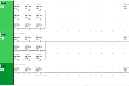
A Ladder Diagram is one of the simplest methods used to program a PLC.
It is a graphical programming language that evolved from electrical relay circuits.
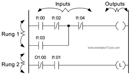
Each program statement is represented with a line, called the rung, that has all relevant inputs to the left and the output to the right.
The output device of a rung is energized if electric power can conceptually flow from the left side of the rung to the right side. Input devices are assumed to block the flow of power if they are not activated.
During the execution of a ladder diagram, the PLC reads the states of all inputs, then determines the states of all outputs starting from the rung at the top side, going down to the last rung, and finally updates the state of the output devices.
Naming Convention
During the development of a PLC program, we must use specific names to identify the inputs, outputs, memory flags, timers, and counters.
PLC manufacturers use a variety of approaches in naming the inputs, outputs and other resources.
A typical naming convention is to identify inputs with the letter “I” and outputs with the letter “O”, followed by a 1-digit number that identifies the slot number and a 2-digit number that identifies the position of the input or output in the slot.
For example:
- I1:00 refers to the first input of slot 1
- O2:00 refers to the first output of slot 2.
Some manufactures number the inputs or outputs starting from 00, while others use the number 01 to identify the first input or output. It is also common to use numbers like 400 e.t.c.
The state of output can be also used as an input in a ladder diagram. In such a case the PLC uses the state of the specific output device that is stored in the output image memory.
Relay Logic Instructions
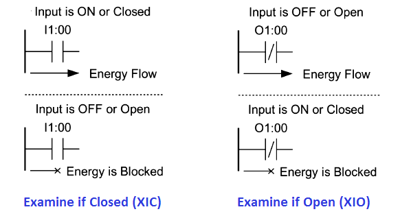
Examine if Closed (XIC)
If the input device is ON or Closed, then the corresponding bit in the data memory (input image) is set to true, thus allowing (conceptually) the energy to flow from its left side to its right-hand side.
Otherwise, it is set to false, thus blocking the energy.
Examine if Open (XIO)
If the input device is OFF or Open, then the corresponding bit in the data memory (input image) is set to true, thus allowing (conceptually) the energy to flow from its left side to its right-hand side.
Otherwise, it is set to false, thus blocking the energy.
Input Transition Sensing Instructions
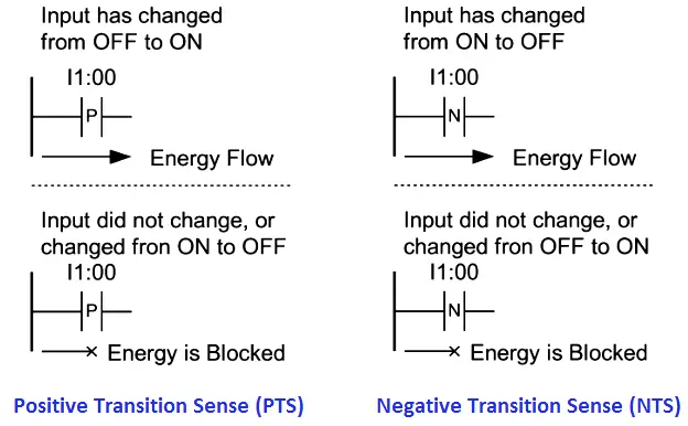
Positive Transition Sense (PTS)
The condition of the right link is ON for one ladder rung evaluation when a change from OFF to ON at the specified input is sensed.
Negative Transition Sense (NTS)
The condition of the right link is ON for one ladder rung evaluation when a change from ON to OFF at the specified input is sensed.
Output Instructions
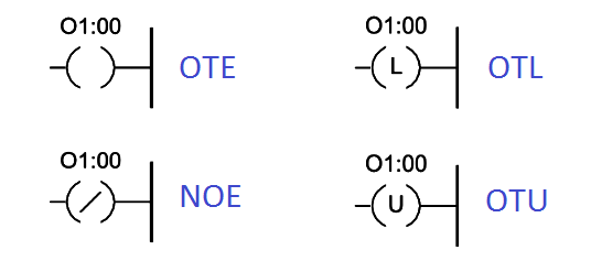
Output Energize (OTE)
If the condition of the left link of the OTE is ON then the corresponding bit in the output data memory is set. The device wired to this output is also energized.
Negative Output Energize (NOE)
If the condition of the left link of the OTE is OFF then the corresponding bit in the output data memory is set. The device wired to this output is also energized.
Output Latch/Set and Output Unlatch/Reset (OTL), (OTU)
If the condition of the left link of the OTL is momentary ON then the corresponding bit in the output data memory is set, and remains set even if the condition switches to the OFF state. The output will remain set until the condition of the left link of the OTU is momentary ON.
Basic Logic Functions
Two Input OR Function

The output is ON if any of the two inputs is ON.
Two Input AND Function

The output is ON if both of the two inputs are ON.
Two Input NAND Function

The output is ON if any of the two inputs is OFF.
Two Input NOR Function

The output is ON if both of the two inputs are OFF.
Two Input EXOR Function

The output is ON if any of the two inputs is ON, but not both.
Two Input EXNOR Function

The output is ON if both of the two inputs are either OFF or ON.
Set/Reset Latch Instructions
Set/Reset Latch using a Hold-in contact

Set/Reset Latch using Latch/Unlatch outputs

Notes:
- O1:00’ means that the output is unchanged
- If both inputs are ON then normally the output is OFF, since the Unlatch rung appears last in the ladder diagram.
Timer Instructions
Timer Instructions are output instructions used to time intervals for which their rung conditions are true (TON), or false (TOF).
These are software timers. Their resolution and accuracy depend on a tick timer maintained by the microprocessor.
Each timer instruction has two values (integers) associated with it:
- Accumulated Value (ACC): This is the current number of ticks (time-base intervals) that have been counted from the moment that the timer has been energized.
- Preset Value (PR): This is a predetermined value set by the programmer. When the accumulated value is equal to, or greater than the preset value, a status bit is set. This bit can be used to control an output device.
Each timer is associated with two status bits:
- Timer Enable Bit (EN): This bit is set when the rung condition to the left of the timer instruction is true. When this bit is set, the accumulated value is incremented on each time-base interval, until it reaches the preset value.
- Done Bit (DN): This bit is set when the accumulated value is equal to the preset value. It is reset when the rung condition becomes false.
Timer On-Delay (TON) Instruction
The TON instruction begins to count when its input rung conditions are true. The accumulated value is reset when the input rung conditions become false.
Timer ladder diagram example:
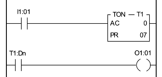
Typical timing diagram (Assume that Preset = 07)

Timer Off-Delay (TOF) Instruction
The TOF instruction begins to count when its input rung makes a true-to-false transition, and continues counting for as long as the input rung remains false. The accumulated value is reset when the input rung conditions become false.
Timer ladder diagram example:
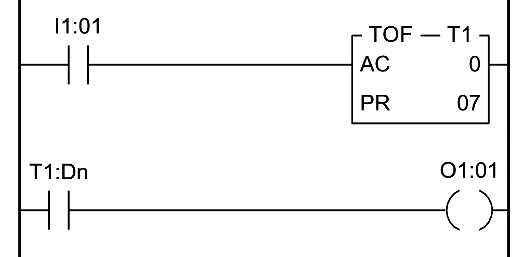
Typical timing diagram (Assume that Preset = 07)

Retentive Timer (RTO) Instruction
The RTO instruction begins to count when its input rung conditions are true. The accumulated value is retained when the input rung conditions become false, and continues counting after the input rung conditions become true.
Timer ladder diagram example:
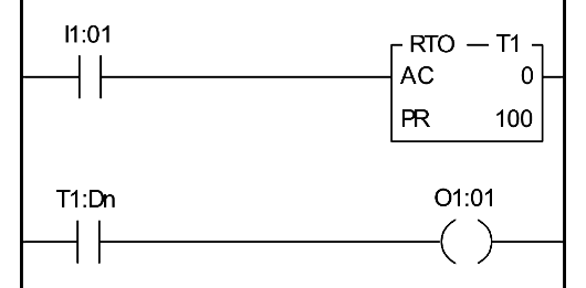
Typical timing diagram (Assume that Preset = 07)

Counter Instructions
Counter Instructions are output instructions used to count false-to-true rung transitions. These transitions are usually caused by events occurring at an input.
These counters can be UP (incrementing) or DOWN (decrementing).
Each counter instruction has two values (integers) associated with it:
- Accumulated Value (ACC): This is the current number of the counter. The initial value is zero.
- Preset Value (PR): This is a predetermined value set by the programmer. When the accumulated value is equal to, or greater than the preset value, a status bit is set. This bit can be used to control an output device.
Each counter is associated with two status bits:
- Counter Enable Bit (EN): This bit is set when a false-to-true rung condition to the left of the counter instruction is detected.
- Done Bit (DN): This bit is set when the accumulated value is equal to the preset value. It is reset when the rung condition becomes false.
The maximum count value is 9999*. After a maximum count is reached, the counters reset and start counting from zero.
Count-up (CTU) Instruction
The CTU instruction increments its accumulated value on each false-to-true transition at its input, starting from 0.
Counter ladder diagram example:
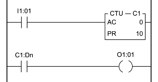
Typical timing diagram (Assume that Preset = 10)

Count-down (CTD) Instruction
The CTD instruction decrements its accumulated value on each false-to-true transition at its input, starting from 0.
Counter ladder diagram example:
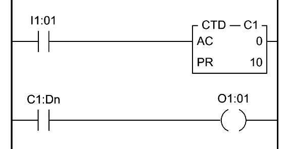
Typical timing diagram (Assume that Preset = -10)

The Reset (RES) Instruction
The RES instruction resets timing and counting instructions.
When the RES instruction is enabled it resets the following:
Counters:
- Accumulated value
- Counter Done Bit
- Counter Enabled Bit
Timers:
- Accumulated value
- Timer Done Bit
- Timer Timing Bit
- Timer Enable Bit
Reset ladder diagram example:

Some other PLC Instructions are :
- Relay-type (Basic) instructions: I, O, OSR, SET, RES, T, C
- Data Handling Instructions:
- Data move Instructions: MOV, COP, FLL, TOD, FRD, DEG, RAD (degrees to radian).
- Comparison instructions: EQU (equal), NEQ (not equal), GEQ (greater than or equal), GRT (greater than).
- Mathematical instructions.
- Continuous Control Instructions ( PID instructions ).
- Program flow control instructions: MCR (master control reset), JMP, LBL, JSR, SBR, RET, SUS, REF
- Specific instructions:
- BSL, BSR (bit shift justify/right), SQO (sequencer output), SQC (sequencer compare), SQL (sequencer load).
- High-speed counter instructions: HSC, HSL, RES, HSE
- Communication instructions: MSQ, SVC
- ASCII instructions: ABL, ACB, ACI, ACL, CAN
Also Read – Advanced PLC Instructions
If you liked this article, then please subscribe to our YouTube Channel for PLC and SCADA video tutorials.
You can also follow us on Facebook and Twitter to receive daily updates.
Read Next:







This GREAT Information!!! Thank You Guys!!!
Awww….This was very helpful and understanding. THANKS