Inst ToolsInst ToolsInst Tools
  • Courses
  • Automation
    • PLC
    • Control System
    • Safety System
    • Communication
    • Fire & Gas System
  • Instrumentation
    • Design
    • Pressure
    • Temperature
    • Flow
    • Level
    • Vibration
    • Analyzer
    • Control Valve
    • Switch
    • Calibration
    • Erection & Commissioning
  • Interview
    • Instrumentation
    • Electrical
    • Electronics
    • Practical
  • Q&A
    • Instrumentation
    • Control System
    • Electrical
    • Electronics
    • Analog Electronics
    • Digital Electronics
    • Power Electronics
    • Microprocessor
  • Request
Search
  • Books
  • Software
  • Projects
  • Process
  • Tools
  • Basics
  • Formula
  • Power Plant
  • Root Cause Analysis
  • Electrical Basics
  • Animation
  • Standards
  • 4-20 mA Course
  • Siemens PLC Course
Reading: How to Operate a Group of Induction Motors using PLC Logic?
Share
Font ResizerAa
Inst ToolsInst Tools
Font ResizerAa
  • Courses
  • Design
  • PLC
  • Interview
  • Control System
Search
  • Courses
  • Automation
    • PLC
    • Control System
    • Safety System
    • Communication
    • Fire & Gas System
  • Instrumentation
    • Design
    • Pressure
    • Temperature
    • Flow
    • Level
    • Vibration
    • Analyzer
    • Control Valve
    • Switch
    • Calibration
    • Erection & Commissioning
  • Interview
    • Instrumentation
    • Electrical
    • Electronics
    • Practical
  • Q&A
    • Instrumentation
    • Control System
    • Electrical
    • Electronics
    • Analog Electronics
    • Digital Electronics
    • Power Electronics
    • Microprocessor
  • Request
Follow US
All rights reserved. Reproduction in whole or in part without written permission is prohibited.
Inst Tools > Blog > Electrical Basics > How to Operate a Group of Induction Motors using PLC Logic?

How to Operate a Group of Induction Motors using PLC Logic?

We will discuss how to make a PLC logic that could handle and control a group of induction motors smoothly and without any problems.

Last updated: January 28, 2023 11:44 am
Hussien Ghareb
Electrical Basics PLC Tutorials
No Comments
Share
5 Min Read
SHARE

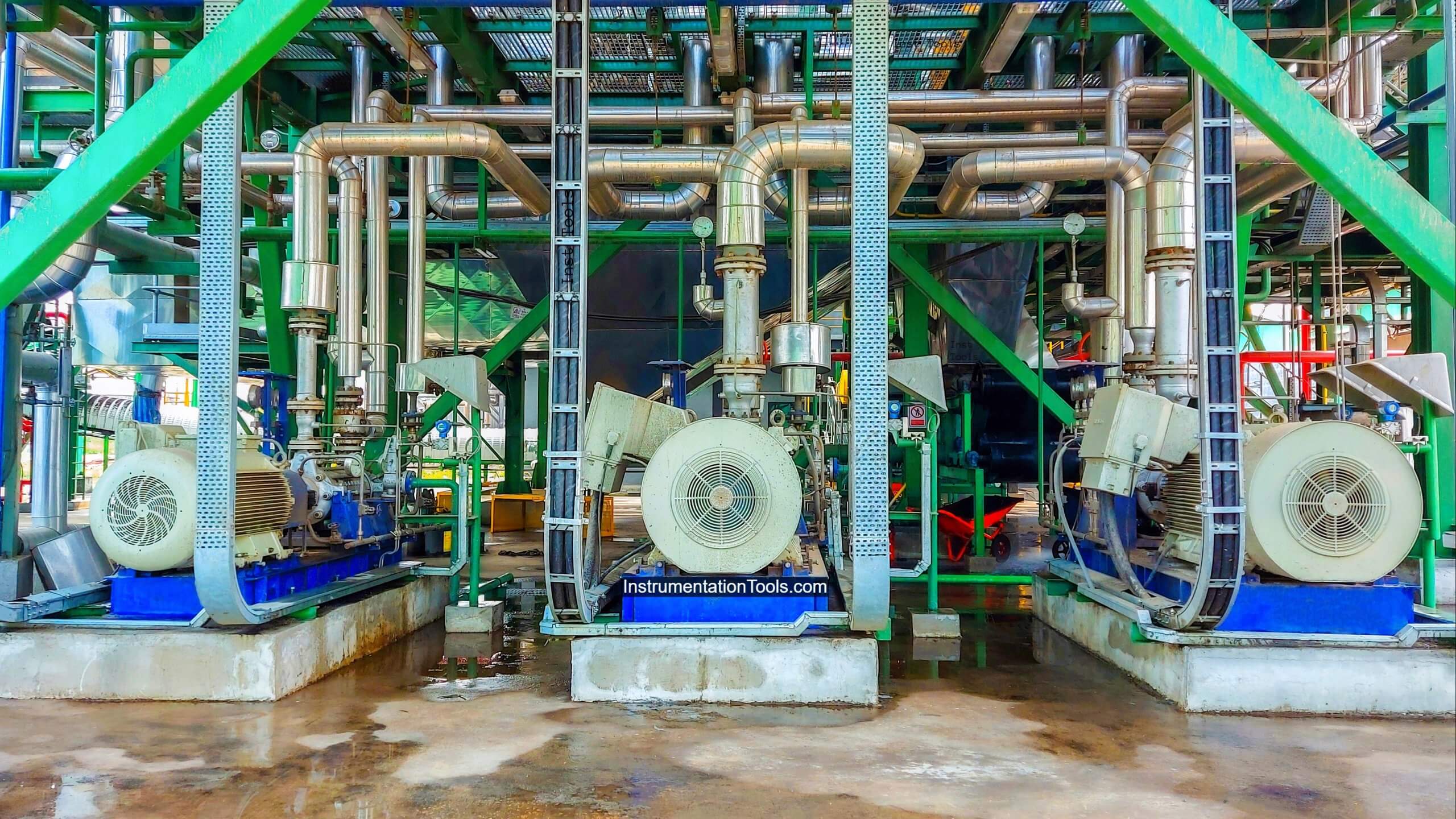
The induction motor is one of the significant elements of any electrical system (production line), as its low costs, operation in a wide range of industrial conditions, and finally, the simple design and rugged construction make them the best in use.

Contents
Induction Motors PLC LogicExample For “Operation of Three Induction Motors”Programming of PLC Code

Induction Motors PLC Logic

Group of Induction Motors

But as we discussed in the previous article earlier, there are some problems that occurred with the miss operating a group of Induction Motors.

So, in this lesson, we will discuss how to make a PLC logic that could handle and control a group of induction motors smoothly and without any problems.

Example For “Operation of Three Induction Motors”

Here we will make a PLC program that can handle the operation of three induction motors that is needed to be operated in a specific order.

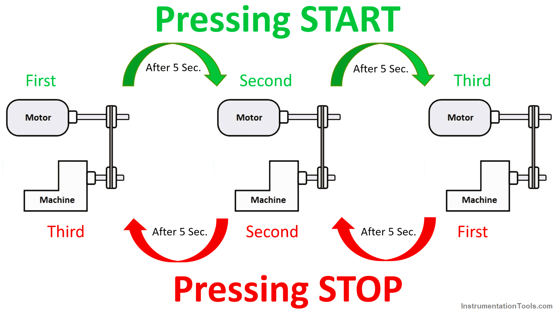
Once the operator presses the start push button the first induction motor will run and after five seconds the second motor will run finally and after additional five seconds the third motor will take the order to run.

After the three motors are running and once the operator presses the stop push button the three motors will stop (with the same periods between each motor) but with an opposite sequence as shown in Fig. (1).

Operation of Three Induction Motors
Figure 1

Programming of PLC Code

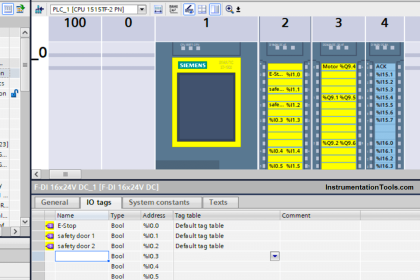
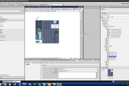
Here we are dealing with SIEMENS PLCs (S7-1200) using the ladder diagram.

Join Siemens PLC Course

Siemens PLC Tia Portal Training Course

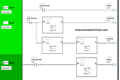
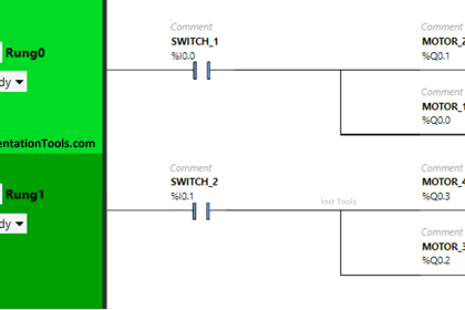
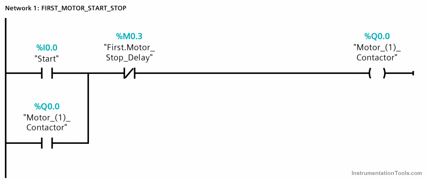
Network 1 – First Motor Start Stop Logic

Once the operator presses the start push button as we can see in Fig. (2), (I0.0) will energize the output coil (Q0.0) that is responsible for turning the first induction motor on.

First Motor Start Stop PLC Code
Figure 2

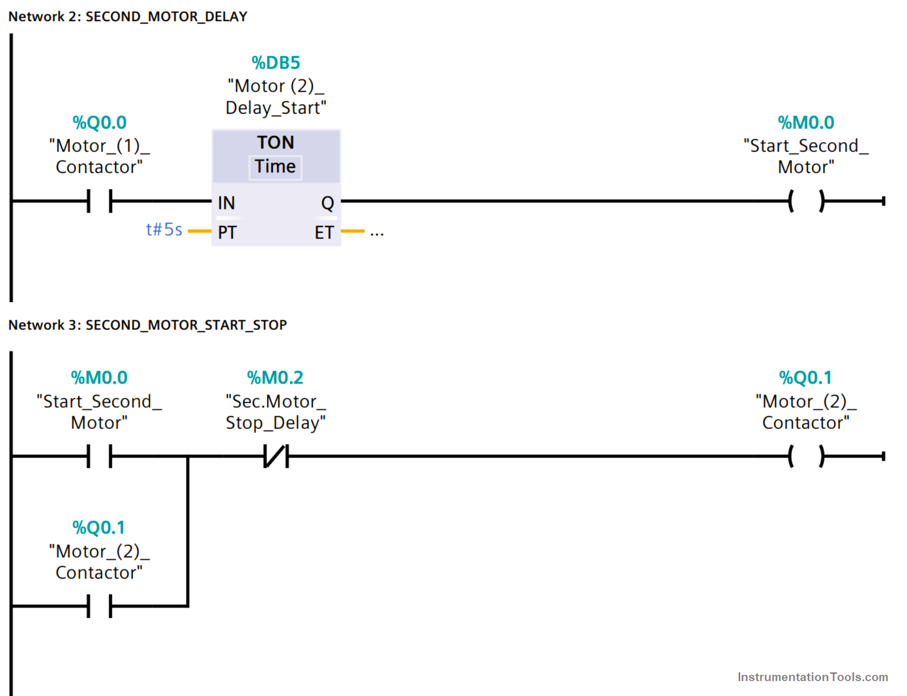
Network 2 – Second Motor Delay Logic

Then after the first motor is turned on (Q0.0), it will start a delay timer (DB5) with a preset time of 5 Seconds.

Network 3 – Second Motor Start Stop Logic

As we can see In Fig. (3) the output of the delay timer (M0.0) will be responsible for turning the second induction motor on (Q0.1), then the motor will latch on itself and it will resume running.

Motor Delay PLC Programming
Figure 3

Network 4 – Third Motor Delay Logic

Then after the second motor is turned on (Q0.1) (NOTE: stop push button is NC) and we did not press the stop push button, the second motor coil (Q0.1) will start a delay timer (DB6) with a preset time of 5 Seconds. As shown in Fig. (4)

Network 5 – Third Motor Start Stop Logic

As we can see In Fig. (4) the output of the delay timer (M0.1) will be responsible for turning the third induction motor on (Q0.2), then the motor will latch on itself and it will resume running.

PLC Induction Motors Start Stop Logic
Figure 4

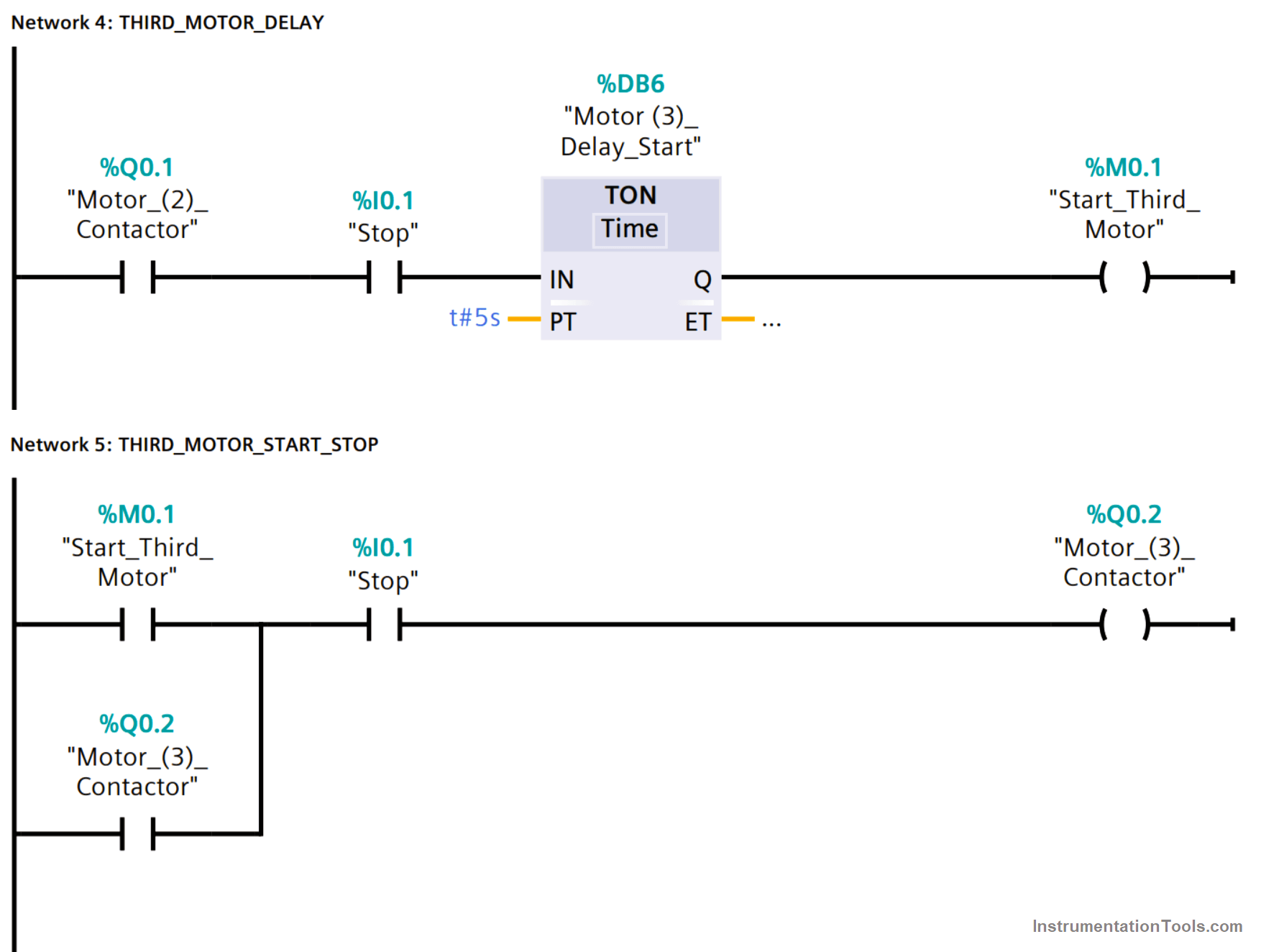
Once the operator presses the stop push button as we can see in Fig. (4), immediately (I0.1) will de-energize the output coil (Q0.2) that is responsible for turning the third induction motor off.

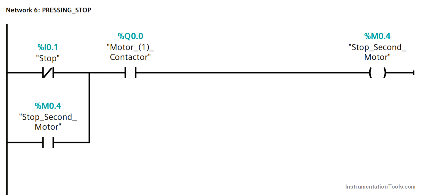
Network 6 – Pressing Stop Logic

Then as shown in Fig. (5) when the operator presses the stop push button, (I0.1) will energize a marker (M0.4)      

Pressing Stop Button PLC Program
Figure 5

Network 7 – Second Motor Stoppage Delay Logic

Then as shown in Fig. (6) when (M0.4) is energized, it will start a delay timer (DB7) with a preset time of 5 Seconds.

The output of the delay timer (M0.2) will be responsible for turning the second induction motor off (Q0.1) as shown in Fig. (3).

PLC Operate Group of Induction Motors Simultaneously
Figure 6

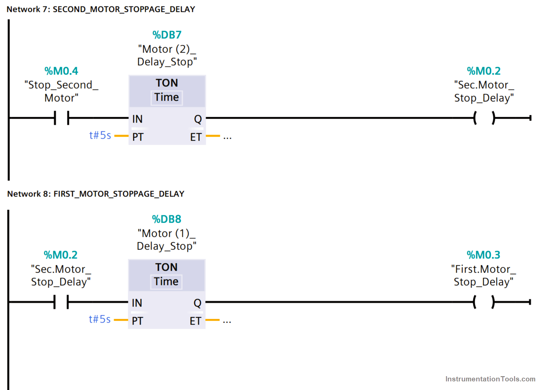
Network 8 – First Motor Stoppage Delay Logic

In addition to de-energizing the second motor (Q0.1), (M0.2) will start a delay timer (DB8) with a preset time of 5 Seconds.

The output of the delay timer (M0.3) will be responsible for turning the first induction motor off (Q0.0) as shown in Fig. (2).

If you liked this article, then please subscribe to our YouTube Channel for Instrumentation, Electrical, PLC, and SCADA video tutorials.

You can also follow us on Facebook and Twitter to receive daily updates.

Read Next:

  • Automation Documents
  • Delta PLC & VFD Modbus
  • Compare PLC and SCADA
  • PLC and DCS System Checks
  • DCS System Maintenance
Don't Miss Our Updates
Be the first to get exclusive content straight to your email.
We promise not to spam you. You can unsubscribe at any time.
Invalid email address
You've successfully subscribed !

Continue Reading

Difference Between PNP and NPN Sensors
Instrumentation Engineer Activities & Documents – Detail Design Phase
PLC Functional Block Diagram for Logic Gates
What is 21 CFR in SCADA and HMI Systems?
How to Select the Right Encoder for Your Machine?
How to do Simulation in Schneider PLC?
Share This Article
Facebook Whatsapp Whatsapp LinkedIn Copy Link
Share
Leave a Comment

Leave a Reply Cancel reply

Your email address will not be published. Required fields are marked *

Stay Connected

128.3kFollowersLike
69.1kFollowersFollow
210kSubscribersSubscribe
38kFollowersFollow

Categories

Explore More

PLC Program for Motor Starter
How to Program PID Control in PLC with Structured Text?
Omron PLC Online Training Course
Move Instruction in Tia Portal
Polarization Index (PI) Test and DA Test
Programmable Logic Controller Maintenance Check Points
PLC Ladder Logic for Tanks Filling as per Priority
PUT Command in Siemens PLC – TIA Portal Basics

Keep Learning

What is a Tag in SCADA

What is a Tag? Types of Tags in SCADA

What is ELCB

What is ELCB? Principle, Advantages, Disadvantages, Applications

DOL Starter Testing

DOL Starter – Working, Circuit, Advantages, Disadvantages, Applications

InTouch SCADA Training Course

Free InTouch SCADA Tutorial Course for Beginners

Start Stop of one Motor from same Push button PLC program

Start Stop of one Motor from the same Push button PLC program

Technical Specification for Uninterrupted Power Supply (UPS) System

Technical Specification for Uninterrupted Power Supply (UPS) System

Three-Phase Power Supply

Single Phase versus Three Phase Power

Difference Between PLC and SCADA

Difference Between PLC and SCADA

Learn More

Classification of Steam Turbines

Classification of Steam Turbines

PLC Programming Example on Multi-Motor Control for Beginners

PLC Programming Example on Multi-Motor Control for Beginners

Industrial Gases

Questions and Answers on Gas

What is Profibus

All About Fieldbus Protocols

Advantages of Valve Regulated Lead Acid (VRLA) Batteries

Advantages of Valve Regulated Lead Acid (VRLA) Batteries

Process Control Instrumentation Objective Questions

Process Control & Instrumentation Objective Questions – Set 1

Free Download Industrial Control System Book

Free Download Industrial Control System Book

Basics of Loop Checks

Basics of Loop Checks

Menu

  • About
  • Privacy Policy
  • Copyright

Quick Links

  • Learn PLC
  • Helping Hand
  • Part Time Job

YouTube Subscribe

Follow US
All rights reserved. Reproduction in whole or in part without written permission is prohibited.
Welcome Back!

Sign in to your account

Username or Email Address
Password

Lost your password?