Inst ToolsInst ToolsInst Tools
  • Courses
  • Automation
    • PLC
    • Control System
    • Safety System
    • Communication
    • Fire & Gas System
  • Instrumentation
    • Design
    • Pressure
    • Temperature
    • Flow
    • Level
    • Vibration
    • Analyzer
    • Control Valve
    • Switch
    • Calibration
    • Erection & Commissioning
  • Interview
    • Instrumentation
    • Electrical
    • Electronics
    • Practical
  • Q&A
    • Instrumentation
    • Control System
    • Electrical
    • Electronics
    • Analog Electronics
    • Digital Electronics
    • Power Electronics
    • Microprocessor
  • Request
Search
  • Books
  • Software
  • Projects
  • Process
  • Tools
  • Basics
  • Formula
  • Power Plant
  • Root Cause Analysis
  • Electrical Basics
  • Animation
  • Standards
  • 4-20 mA Course
  • Siemens PLC Course
Reading: Identify Two Pressure Switches Logic
Share
Font ResizerAa
Inst ToolsInst Tools
Font ResizerAa
  • Courses
  • Design
  • PLC
  • Interview
  • Control System
Search
  • Courses
  • Automation
    • PLC
    • Control System
    • Safety System
    • Communication
    • Fire & Gas System
  • Instrumentation
    • Design
    • Pressure
    • Temperature
    • Flow
    • Level
    • Vibration
    • Analyzer
    • Control Valve
    • Switch
    • Calibration
    • Erection & Commissioning
  • Interview
    • Instrumentation
    • Electrical
    • Electronics
    • Practical
  • Q&A
    • Instrumentation
    • Control System
    • Electrical
    • Electronics
    • Analog Electronics
    • Digital Electronics
    • Power Electronics
    • Microprocessor
  • Request
Follow US
All rights reserved. Reproduction in whole or in part without written permission is prohibited.
Inst Tools > Blog > Practical Questions > Identify Two Pressure Switches Logic

Identify Two Pressure Switches Logic

Last updated: September 30, 2017 4:19 am
Editorial Staff
Practical Questions
No Comments
Share
1 Min Read
SHARE

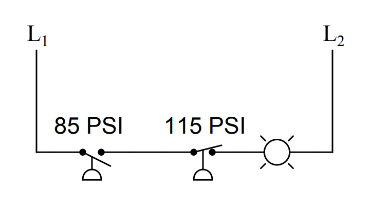
Two pressure switches are plumbed together so as to receive the exact same pressure at all times, and they both sense the pressure of compressed air in a pneumatic system. Based on the wiring diagram for these switches, identify the function of the lamp:

Two pressure switches

Answer : 

The lamp’s illumination signifies a condition where the compressed air pressure is somewhere between 85 and 115 PSI.

The lamp will turn off if the pressure drops below 85 PSI or if the pressure rises above 115 PSI.

Share Your Answer / Comments

Credits : by Tony R. Kuphaldt – under CC BY 1.0

Don't Miss Our Updates
Be the first to get exclusive content straight to your email.
We promise not to spam you. You can unsubscribe at any time.
Invalid email address
You've successfully subscribed !

Continue Reading

Pneumatic Force Balance Instrument
Flow Transmitter Readings mismatch with DCS
Pneumatic Moment-balance Differential Pressure Transmitter
Identify the Problem in the PLC Program
Flapper Nozzle Questions
Differential Pressure Transmitter with 5 Way Manifold Valve
Share This Article
Facebook Whatsapp Whatsapp LinkedIn Copy Link
Share
Leave a Comment

Leave a Reply Cancel reply

Your email address will not be published. Required fields are marked *

Stay Connected

128.3kFollowersLike
69.1kFollowersFollow
210kSubscribersSubscribe
38kFollowersFollow

Categories

Explore More

Resistance Temperature Detector (RTD) Questions – 1
Questions on Allen-Bradley MicroLogix 1000 PLC
Solenoid-controlled Valve Problem
How to Draw a Schematic Diagram ?
PT Loop Diagram Faults
Fisher model 546 I/P transducer
Problem on Solar Hot Air Collector and Variable Speed Fan
How to Decrease Span of Pressure Gauge?

Keep Learning

Calculate Hydrostatic Pressure of a vertical column of Acetic Acid

Hydrostatic Pressure of a vertical column of Acetic Acid

calibrating low-pressure instrument

Simulate Different Values for Pressure Instrument Under Test

Process Switches Normal Status

Define Normal Status for each of the Process Switch

Programmable Logic Controller (PLC) Questions and Answers

Programmable Logic Controller (PLC) Questions and Answers – 5

Siemens PLC Block Diagram

Programmable Logic Controller (PLC) Questions and Answers – 14

hydrostatic interface measurement calculation

Hydrostatic Pressure Measurement Questions

Strain Gauge Bridge Circuit

Something is Wrong with Strain Gauge Bridge Circuit

Explain What these Spool Valve Represent

Explain What these Spool Valve Symbols Represent?

Learn More

On Off Valve Root Cause Analysis

Root Cause Analysis for FRP Line Damaged due to On-Off Valve

Transformer Open and Short Circuit Tests

Flow Meter Hook Up

Flow Meter Installation Guidelines

different flow measurement technologies

Different Flow Measurement Technologies

MOSFET VI Characteristics

Power MOSFET

Transformers Questions and Answers

Latest Transformers Questions and Answers

Interface Level Measurement Selection Guide

Interface Level Measurement Selection Guide

TIA Portal Options

How to Troubleshoot Siemens PLC Programs?

Menu

  • About
  • Privacy Policy
  • Copyright

Quick Links

  • Learn PLC
  • Helping Hand
  • Part Time Job

YouTube Subscribe

Follow US
All rights reserved. Reproduction in whole or in part without written permission is prohibited.
Welcome Back!

Sign in to your account

Username or Email Address
Password

Lost your password?