Inst ToolsInst ToolsInst Tools
  • Courses
  • Automation
    • PLC
    • Control System
    • Safety System
    • Communication
    • Fire & Gas System
  • Instrumentation
    • Design
    • Pressure
    • Temperature
    • Flow
    • Level
    • Vibration
    • Analyzer
    • Control Valve
    • Switch
    • Calibration
    • Erection & Commissioning
  • Interview
    • Instrumentation
    • Electrical
    • Electronics
    • Practical
  • Q&A
    • Instrumentation
    • Control System
    • Electrical
    • Electronics
    • Analog Electronics
    • Digital Electronics
    • Power Electronics
    • Microprocessor
  • Request
Search
  • Books
  • Software
  • Projects
  • Process
  • Tools
  • Basics
  • Formula
  • Power Plant
  • Root Cause Analysis
  • Electrical Basics
  • Animation
  • Standards
  • 4-20 mA Course
  • Siemens PLC Course
Reading: How to Test Diodes Using Multimeter
Share
Font ResizerAa
Inst ToolsInst Tools
Font ResizerAa
  • Courses
  • Design
  • PLC
  • Interview
  • Control System
Search
  • Courses
  • Automation
    • PLC
    • Control System
    • Safety System
    • Communication
    • Fire & Gas System
  • Instrumentation
    • Design
    • Pressure
    • Temperature
    • Flow
    • Level
    • Vibration
    • Analyzer
    • Control Valve
    • Switch
    • Calibration
    • Erection & Commissioning
  • Interview
    • Instrumentation
    • Electrical
    • Electronics
    • Practical
  • Q&A
    • Instrumentation
    • Control System
    • Electrical
    • Electronics
    • Analog Electronics
    • Digital Electronics
    • Power Electronics
    • Microprocessor
  • Request
Follow US
All rights reserved. Reproduction in whole or in part without written permission is prohibited.
Inst Tools > Blog > Electronic Basics > How to Test Diodes Using Multimeter

How to Test Diodes Using Multimeter

Last updated: April 27, 2017 4:22 am
Editorial Staff
Electronic Basics
3 Comments
Share
5 Min Read
SHARE

How to test diodes

Digital multimeters can test diodes using one of two methods:

  1. Diode Test mode: almost always the best approach.
  2. Resistance mode: typically used only if a multimeter is not equipped with a Diode Test mode.

Note: In some cases it may be necessary to remove one end of the diode from the circuit in order to test the diode.

Things to know about the Resistance mode when testing diodes:

  • Does not always indicate whether a diode is good or bad.
  • Should not be taken when a diode is connected in a circuit since it can produce a false reading.
  • Can be used to verify a diode is bad in a specific application after a Diode Test indicates a diode is bad.

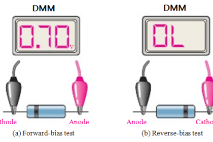
A diode is best tested by measuring the voltage drop across the diode when it is forward-biased. A forward-biased diode acts as a closed switch, permitting current to flow.

A multimeter’s Diode Test mode produces a small voltage between test leads. The multimeter then displays the voltage drop when the test leads are connected across a diode when forward-biased.

How to Test Diodes Using Multimeter

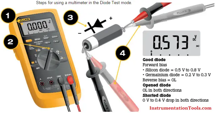
The Diode Test procedure is conducted as follows:

  1. Make certain a) all power to the circuit is OFF and b) no voltage exists at the diode. Voltage may be present in the circuit due to charged capacitors. If so, the capacitors need to be discharged. Set the multimeter to measure ac or dc voltage as required.
  2. Turn the dial (rotary switch) to Diode Test mode. It may share a space on the dial with another function.
  3. Connect the test leads to the diode. Record the measurement displayed.
  4. Reverse the test leads. Record the measurement displayed.

Diode test analysis

  • A good forward-based diode displays a voltage drop ranging from 0.5 to 0.8 volts for the most commonly used silicon diodes. Some germanium diodes have a voltage drop ranging from 0.2 to 0.3 V.
  • The multimeter displays OL when a good diode is reverse-biased. The OL reading indicates the diode is functioning as an open switch.
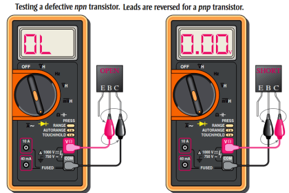
  • A bad (opened) diode does not allow current to flow in either direction. A multimeter will display OL in both directions when the diode is opened.
  • A shorted diode has the same voltage drop reading (approximately 0.4 V) in both directions.

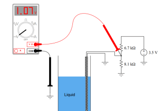
A multimeter set to the Resistance mode (Ω) can be used as an additional diode test or, as mentioned previously, if a multimeter does not include the Diode Test mode.

Diode Forward Bias and Reverse Bias

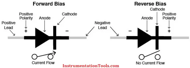
A diode is forward-biased when the positive (red) test lead is on the anode and the negative (black) test lead is on the cathode.

  • The forward-biased resistance of a good diode should range from 1000 Ω to 10 MΩ.
  • The resistance measurement is high when the diode is forward-biased because current from the multimeter flows through the diode, causing the high-resistance measurement required for testing.

A diode is reverse-biased when the positive (red) test lead is on the cathode and the negative (black) test lead is on the anode.

  • The reverse-biased resistance of a good diode displays OL on a multimeter. The diode is bad if readings are the same in both directions.

Testing Diode using resistance

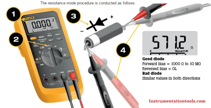
The resistance mode procedure is conducted as follows:

  1. Make certain a) all power to the circuit is OFF and b) no voltage exists at the diode. Voltage may be present in the circuit due to charged capacitors. If so, the capacitors need to be discharged. Set the multimeter to measure ac or dc voltage as required.
  2. Turn the dial to Resistance mode (Ω). It may share a space on the dial with another function.
  3. Connect the test leads to the diode after it has been removed from the circuit. Record the measurement displayed.
  4. Reverse the test leads. Record the measurement displayed.
  5. For best results when using the Resistance mode to test diodes, compare the readings taken with a known good diode.

Source : Fluke

Also Read: Logic Gates Animation

Don't Miss Our Updates
Be the first to get exclusive content straight to your email.
We promise not to spam you. You can unsubscribe at any time.
Invalid email address
You've successfully subscribed !

Continue Reading

How to Identify the Transistor Terminals
How are Silicon Chips Disposed?
Zener Diode Voltage Regulators
How to do Continuity Testing using Multimeter
How to Measure AC Voltage using Multimeter
How to Measure Duty Cycle using Multimeter
Share This Article
Facebook Whatsapp Whatsapp LinkedIn Copy Link
Share
3 Comments
  • Ahmed says:
    March 9, 2016 at 1:16 pm

    Great article.

    Reply
  • dheeraj dhawas says:
    March 15, 2016 at 8:58 am

    Dear sir,

    please tell me how can we measure the NO and NC contact in a multimeter

    Reply
    • S Bharadwaj Reddy says:
      March 15, 2016 at 3:38 pm

      Hello, Its a Basic Question. Generally we use Continuity Option in Multimeter. (Considering NO & NC are Dry Contacts).

      Reply

Leave a Reply Cancel reply

Your email address will not be published. Required fields are marked *

Stay Connected

128.3kFollowersLike
69.1kFollowersFollow
210kSubscribersSubscribe
38kFollowersFollow

Categories

Explore More

What is an Inductor? – Types of Inductors
What is Contactor ?
How to Test a Battery using a Multimeter?
Top Beginner Soldering Mistakes and How to Avoid Them?
Types of Noise in Electronics
Types of Potentiometers – What is a Potentiometer? – Applications
Testing a Transistor with a Digital Multimeter
What is an Electrical Wire Mesh?

Keep Learning

Tank car bonding at siding

Electrical Static Grounding Techniques

Switched Mode Power Supply (SMPS)

How does SMPS Works? – Switched Mode Power Supply

Voltage Regulator Circuit

Basics of Voltage Regulator

Seven Segment LED Display

Difference Between Common Cathode and Common Anode 7 Segment LED Display?

How to Test a Transistor

How to Test a Transistor ?

What is a Fuse

What is a Fuse ?

What is PCB Corrosion - Electronic Boards Corrosion Prevention

What is PCB Corrosion? Electronic Boards Corrosion Prevention

Difference between Analog Signal and Digital Signal

What are Analog and Digital Signals? Differences, Examples

Learn More

Installation Precautions of Thermocouple and RTD

Installation Precautions of Thermocouple and RTD

PLC Power Supply and Operating Voltages

PLC Power Supply and Operating Voltages

Displacement Level Transmitter in situ calibration

Displacer (buoyancy) Level Transmitter Principle, Limitations, Design, Installation & Calibration

Voltage Control Methods at Distribution System

Factors affect Voltage Level Selection in Service System

PLC Program for 2 Push buttons to Control 1 Output

PLC Program for 2 Push buttons to Control 1 Output

Conductivity measurement

Conductivity Measurement

Types of active transducers

Types of Transducers in Instrumentation

PLC Program Upload

How to Upload Siemens PLC Programs?

Menu

  • About
  • Privacy Policy
  • Copyright

Quick Links

  • Learn PLC
  • Helping Hand
  • Part Time Job

YouTube Subscribe

Follow US
All rights reserved. Reproduction in whole or in part without written permission is prohibited.
Welcome Back!

Sign in to your account

Username or Email Address
Password

Lost your password?