Inst ToolsInst ToolsInst Tools
  • Ask
  • Courses
  • Videos
  • Q & A
    • Interview
      • Instrumentation
      • Electronics
      • Electrical
      • Practical Questions
    • MCQ
      • Instrumentation MCQ
      • Electrical MCQ
      • Electronics MCQ
      • Control Systems MCQ
      • Analog Electronics MCQ
      • Digital Electronics MCQ
      • Power Electronics MCQ
      • Microprocessor MCQ
      • Multiple Choice Questions
  • EE
    • Electronics
      • Electronics Q & A
      • Electronic Basics
      • Electronic Devices & Circuits
      • Electronics Animation
      • Digital Electronics
    • Electrical
      • Electrical Basics
      • Electrical Q & A
      • Power Electronics
      • Electrical Machines
      • Electrical Animation
      • Power Systems
      • Switchgear & Protection
      • Transmission & Distribution
  • Measure
    • Control Valves
    • Calibration
    • Temperature
    • Pressure
    • Flow
    • Level
    • Analyzers
    • Switches
    • Vibration
    • Solenoid Valve
  • Control
    • PLC Tutorials
    • Control Systems
    • Safety Instrumented System (SIS)
    • Communication
    • Fire & Gas System
  • More
    • Design
    • Tools
    • Animation
    • Basics
    • Formulas
    • Standards
    • TextBooks
    • Common
    • Software
    • Excel Tools
    • Erection & Commissioning
    • Process Fundamentals
    • Videos
    • Books
Search
All rights reserved. Reproduction in whole or in part without written permission is prohibited.
Reading: How to Test a Transistor ?
Share
Notification Show More
Font ResizerAa
Inst ToolsInst Tools
Font ResizerAa
  • Courses
  • PLC Tutorials
  • Control Systems
Search
  • Ask
  • Courses
  • Videos
  • Q & A
    • Interview
    • MCQ
  • EE
    • Electronics
    • Electrical
  • Measure
    • Control Valves
    • Calibration
    • Temperature
    • Pressure
    • Flow
    • Level
    • Analyzers
    • Switches
    • Vibration
    • Solenoid Valve
  • Control
    • PLC Tutorials
    • Control Systems
    • Safety Instrumented System (SIS)
    • Communication
    • Fire & Gas System
  • More
    • Design
    • Tools
    • Animation
    • Basics
    • Formulas
    • Standards
    • TextBooks
    • Common
    • Software
    • Excel Tools
    • Erection & Commissioning
    • Process Fundamentals
    • Videos
    • Books
Follow US
All rights reserved. Reproduction in whole or in part without written permission is prohibited.
Inst Tools > Blog > Electronic Basics > How to Test a Transistor ?

How to Test a Transistor ?

Last updated: December 29, 2020 11:27 pm
Editorial Staff
Electronic Basics
No Comments
Share
4 Min Read
SHARE

An individual transistor can be tested either in-circuit or out-of-circuit with a transistor tester. For example, let’s say that an amplifier on a particular printed circuit (PCB) board has malfunctioned. Good troubleshooting practice dictates that you do not unsolder a component from a circuit board unless you are reasonably sure that it is bad or you simply cannot isolate the problem down to a single component. When components are removed, there is a risk of damage to the PC board contacts and traces.

You can perform an in-circuit check of the transistor using a transistor tester similar to the one shown in below Figure. The three clip-leads are connected to the transistor terminals and the tester gives a positive indication if the transistor is good.

In-Circuit and Out-of-Circuit Tests

Case 1

If the transistor tests defective, it should be carefully removed and replaced with a known good one. An out-of-circuit check of the replacement device is usually a good idea, just to make sure it is OK. The transistor is plugged into the socket on the transistor tester for out-of-circuit tests.

Case 2

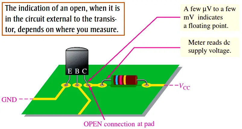
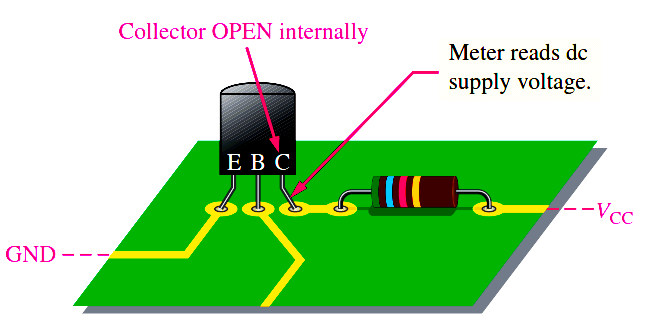
If the transistor tests good in-circuit but the circuit is not working properly, examine the circuit board for a poor connection at the collector pad or for a break in the connecting trace. A poor solder joint often results in an open or a highly resistive contact. The physical point at which you actually measure the voltage is very important in this case. For example, if you measure on the collector lead when there is an external open at the collector pad, you will measure a floating point. If you measure on the connecting trace or on the RC lead, you will read VCC. This situation is illustrated in Below Figure.

how-to-test-a-transistor

Importance of Point-of-Measurement in Troubleshooting

In case 2, if you had taken the initial measurement on the transistor lead itself and the open were internal to the transistor as shown in Below Figure, you would have measured VCC. This indicates a defective transistor even before the tester was used, assuming the base-to-emitter voltage is normal. This simple concept emphasizes the importance of point-of-measurement in certain troubleshooting situations.
transistor-fault-identification


Leakage Measurement

Very small leakage currents exist in all transistors and in most cases are small enough to neglect (usually nA). When a transistor is connected with thebase open (IB = 0), it is in cutoff. Ideally IC = 0; but actually there is a small current from collector to emitter, as mentioned earlier, called ICEO (collector-to-emitter current with base open). This leakage current is usually in the nA range. A faulty transistor will often have excessive leakage current and can be checked in a transistor tester. Another leakage current in transistors is the reverse collector-to-base current, ICBO. This is measured with the emitter open. If it is excessive, a shorted collector-base junction is likely.

Gain Measurement

In addition to leakage tests, the typical transistor tester also checks the βDC. A known value of IB is applied, and the resulting IC is measured. The reading will indicate the value of the IC /IB ratio, although in some units only a relative indication is given. Most testers provide for an in-circuit βDC check, so that a suspected device does not have to be removed from the circuit for testing.

Curve Tracers

A curve tracer is an oscilloscope type of instrument that can display transistor characteristics such as a family of collector curves. In addition to the measurement and display of various transistor characteristics, diode curves can also be displayed.
How to Test a Transistor
Don't Miss Our Updates
Be the first to get exclusive content straight to your email.
We promise not to spam you. You can unsubscribe at any time.
Invalid email address
You've successfully subscribed !
Factors Affecting Inductance
Troubleshooting a Power Supply Circuit
How to Identify the Transistor Terminals
What is PCB Corrosion? Electronic Boards Corrosion Prevention
Difference between Intrinsic and Extrinsic Semiconductors
Share This Article
Facebook Whatsapp Whatsapp LinkedIn Copy Link
Share
Leave a Comment

Leave a Reply Cancel reply

Your email address will not be published. Required fields are marked *

Stay Connected

128.3kFollowersLike
69.1kFollowersFollow
208kSubscribersSubscribe
38kFollowersFollow

Categories

Recent Comments

  • Guifty Shimica on Top Non-PLC Certification Courses for Automation Professionals
  • Guifty Shimica on Top Non-PLC Certification Courses for Automation Professionals
  • MIHARITSOA Aina Sitraka on Top Non-PLC Certification Courses for Automation Professionals
  • Vaishnavi on Free Instrumentation Course for Trainee Engineers

Related Articles

Voltage Regulator Circuit

Basics of Voltage Regulator

How to Test a Battery using Multimeter

How to Test a Battery using a Multimeter?

Zener Diode Regulator

Zener Diode Voltage Regulators

Difference Between Clamp Meters and Digital Multimeters

Difference Between Clamp Meters and Multimeters

Transistor as Switch Working Animation

How a Transistor Switch Works

Measure Frequency using Multimeter

How to measure frequency using Multimeter

Seven Segment LED Display

Difference Between Common Cathode and Common Anode 7 Segment LED Display?

Difference Between LED and LCD

Difference Between LED and LCD

More Articles

Retentive ON delay timer using PLC Logic

Retentive ON Delay Timer using PLC

Scaling in PLC

How to do Scaling for Analog Input in RSLogix 500?

Displacer Level Measurement Formula

Displacer Level Measurement Calculations

How to Select a Inductive Proximity Sensor

How to Select a Inductive Proximity Sensor

Wet Dust Suppression system

Wet Dust Suppression System

Solar-Based Engineering Projects

Top 100 Solar-Based Engineering Projects

TOC Analyzer Principle

Total Organic Carbon Analyzer Principle

Control valve performance with constant pressure

Control Valve Performance with Constant Pressure

Follow US
All rights reserved. Reproduction in whole or in part without written permission is prohibited.
Welcome Back!

Sign in to your account

Username or Email Address
Password

Lost your password?