When you design a SCADA or HMI system, there are instances when many screens tend to repeat themselves, due to the same information everywhere.
For example, if there are 10 motors and every motor has the same information in it, many programmers create 10 different screens for them. But, there also comes a feature in HMI or SCADA, called a faceplate. It is a common screen where you have to indirect address the motors by linking the variables, and the corresponding motor data will be communicated. You need not have to create multiple screens for them.
A motor is the most commonly used equipment in industrial automation, and it is important to see how you design a motor faceplate in the graphics. This can help the user provide relevant information.
In this post, we will learn how to design a motor faceplate in SCADA or HMI graphics.
First of all, let us understand what a faceplate is. A faceplate can be termed as a common screen or popup, in which indirect addresses are defined. Whenever you call one faceplate of an object, its corresponding values are moved and shared with the faceplate. And when you call the faceplate of suppose the fourth object, then its corresponding values are moved and shared with the faceplate.
In short, the SCADA screen is the same; just need to create multiple instances and tag the corresponding variables in it. Whenever an instance is called, the tags in it are shared with the faceplate. This reduces the need to design multiple screens and popups for the same.
Because you create only a single screen or popup, the programming size also reduces, and indirectly, the programming work also reduces. Because, if suppose there are 20 objects having the same data to be shared; then there is no use to create 20 screens or popups of the same. It is an utter waste of time and energy. Instead, just create a single screen and link internal variables in it. These internal variables will be overwritten by external variables upon calling it through any instance.
This concept is very similar to a library you create in PLC programming. When the logic is the same for many types, you just create a single library for that type, instead of writing the logic multiple times. This saves time and energy in writing logic.
Refer to the below image for understanding. As you can see, all the general information is present in the faceplate.
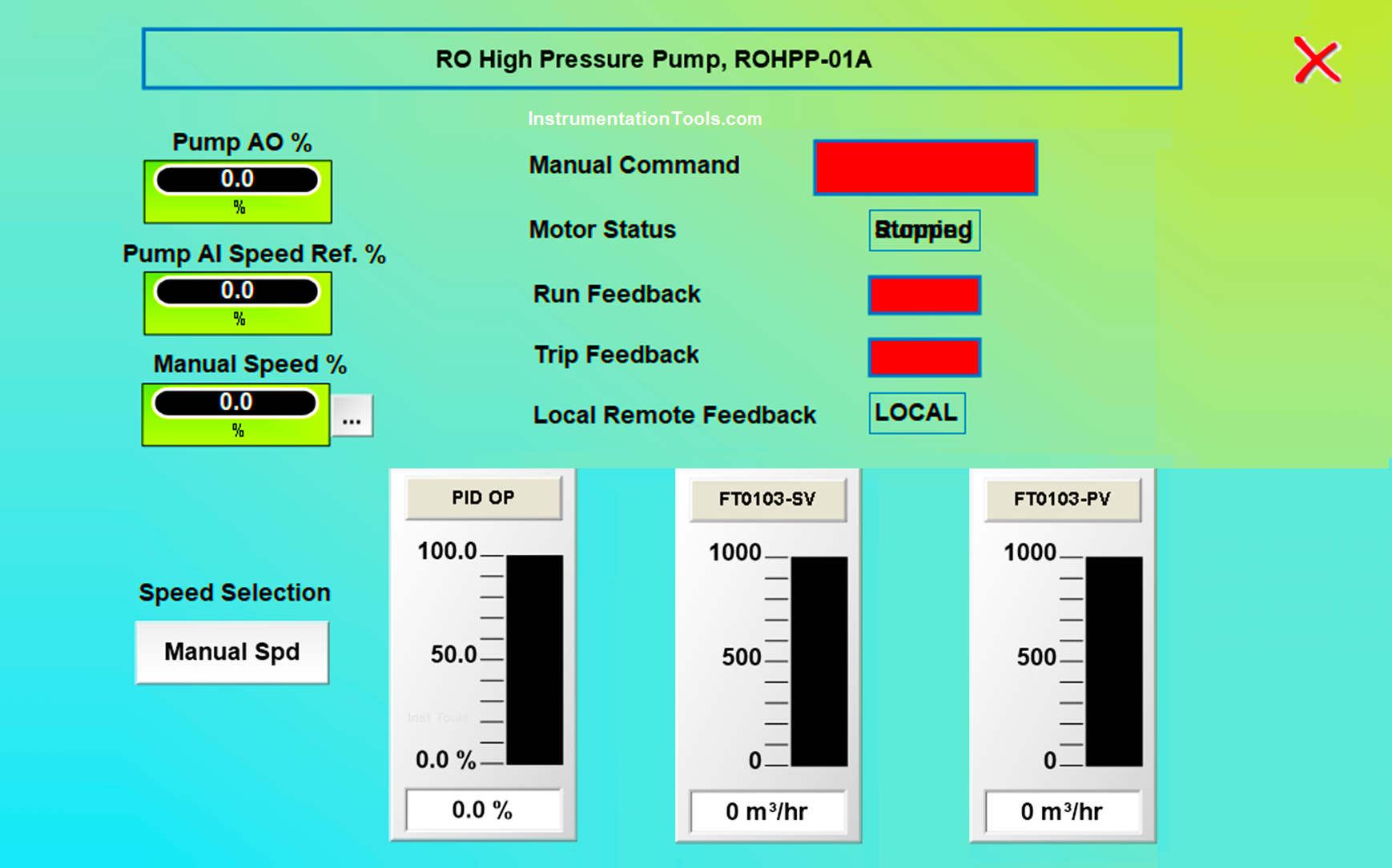
Let us have a look at some of the most common data that can be shown in the popup:
These are some of the most general types of data shown in the motor faceplate. There are other data too, like alarm status, running hour status, motor temperature, or energy consumption data. It varies on programmer to programmer and what is the client requirement.
If you liked this article, then please subscribe to our YouTube Channel for Instrumentation, Electrical, PLC, and SCADA video tutorials.
You can also follow us on Facebook and Twitter to receive daily updates.
Read Next:
In this post, we will learn the basic requirements for a network switch to be…
The PLC panel and MCC panel interface signals are start, stop, run feedback, trip, local…
In this article, we are going to discuss about shutter door control using induction motor…
Electrical Drives control the motion of electric motors. Motion control is required in industrial and…
PLC ladder logic design to control 3 motors with toggle switch and explain the program…
VFD simulator download: Master the online tool from the Yaskawa V1000 & programming software for…
