Inst ToolsInst ToolsInst Tools
  • Courses
  • Automation
    • PLC
    • Control System
    • Safety System
    • Communication
    • Fire & Gas System
  • Instrumentation
    • Design
    • Pressure
    • Temperature
    • Flow
    • Level
    • Vibration
    • Analyzer
    • Control Valve
    • Switch
    • Calibration
    • Erection & Commissioning
  • Interview
    • Instrumentation
    • Electrical
    • Electronics
    • Practical
  • Q&A
    • Instrumentation
    • Control System
    • Electrical
    • Electronics
    • Analog Electronics
    • Digital Electronics
    • Power Electronics
    • Microprocessor
  • Request
Search
  • Books
  • Software
  • Projects
  • Process
  • Tools
  • Basics
  • Formula
  • Power Plant
  • Root Cause Analysis
  • Electrical Basics
  • Animation
  • Standards
  • 4-20 mA Course
  • Siemens PLC Course
Reading: How to Control VFD with PLC using Ladder Logic
Share
Font ResizerAa
Inst ToolsInst Tools
Font ResizerAa
  • Courses
  • Design
  • PLC
  • Interview
  • Control System
Search
  • Courses
  • Automation
    • PLC
    • Control System
    • Safety System
    • Communication
    • Fire & Gas System
  • Instrumentation
    • Design
    • Pressure
    • Temperature
    • Flow
    • Level
    • Vibration
    • Analyzer
    • Control Valve
    • Switch
    • Calibration
    • Erection & Commissioning
  • Interview
    • Instrumentation
    • Electrical
    • Electronics
    • Practical
  • Q&A
    • Instrumentation
    • Control System
    • Electrical
    • Electronics
    • Analog Electronics
    • Digital Electronics
    • Power Electronics
    • Microprocessor
  • Request
Follow US
All rights reserved. Reproduction in whole or in part without written permission is prohibited.
Inst Tools > Blog > PLC Tutorials > How to Control VFD with PLC using Ladder Logic

How to Control VFD with PLC using Ladder Logic

Last updated: March 4, 2021 3:16 pm
Editorial Staff
PLC Tutorials
7 Comments
Share
4 Min Read
SHARE

This is a complete tutorial about PLC ladder logic to control variable frequency drive (VFD) for motor speed control with speed selection from Field Local Panel or SCADA graphics.

Contents
How to Control VFD with PLC ?Control and Power DiagramCommissioning and Parameters Programming in VFD PLC ProgramNetwork 1 :Network 2 :Network 3 :Network 4 :Network 5 :Network 6 :SCADA DesignNormal StateRunning StateError State

Execution Steps :

  1. Prepare a Control and Power drawing
  2. Commissioning and Parameters Programming in VFD
  3. Prepare a PLC program
  4. Prepare a SCADA design

How to Control VFD with PLC ?

How to Control VFD with PLC using Ladder Logic

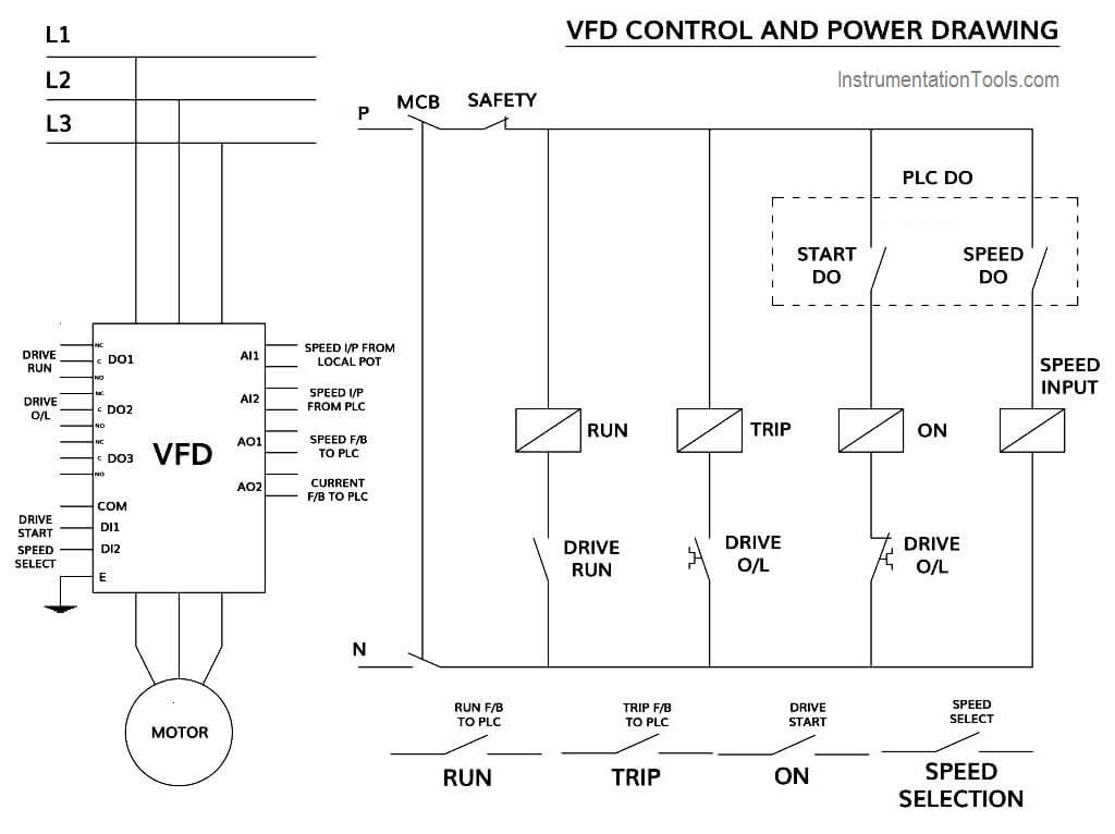
Control and Power Diagram

VFD connections with PLC

Commissioning and Parameters Programming in VFD

  • Commissioning is needed for the proper function of VFD.
  • Necessary parameter like Motor Nameplate details, Input Voltage, Motor Type, Frequency should be entered in VFD during quick commissioning.
  • After successful quick commissioning, now it’s a time to install the advanced commissioning. This commissioning is needed to give the details of all the digital and analog inputs and outputs, like
    • Information about Digital inputs of Start command and Speed Selection command
    • Information about Digital Outputs like Status of Drive Running and Drive in Fault etc.
    • Information about Analog Inputs like Speed Input 1 and Speed Input 2
    • Information about Analog Outputs like Current and Frequency of Motor

 PLC Program

Network 1 :

VFD Ready to Start

In this Network 1, we are checking whether the VFD is ready to start. This signal will come when all the conditions are healthy as well as safety and power feedbacks are active.

Network 2 :

VFD Start Button in Ladder Logic

In the Network 2, When start button is pressed, VFD Drive_DO bit will be set, if Ready_to_Start and No Error will be there.

Network 3 :

VFD Stop Logic in PLC

This is the stop logic, When stop button is pressed it will reset the Drive_DO bit.

Network 4 :

VFD Run Feedback Fault PLC Logic

In this Network 4, this logic is required for safety as soon as Drive_DO bit will set and if any case VFD will not operate due to any fault then after predefined wait time, here we considered it as Run_FB_Time, it will reset the Drive_DO bit and generate Error.

This Error you can acknowledge from the SCADA after resolving the error from the field side.

Network 5 :

Variable Frequency Drive Overload Error Logic

In this Network 5, If the VFD is taking more current and gives overload error, then it will reset Drive_DO bit and generate Error.

This Error you can acknowledge from the SCADA after resolving the error from the field side.

Network 6 :

Drive speed selection Ladder Diagram

This is the speed selection Digital output, if you select speed input as a local then it will not activate Speed Selection bit resulting Speed_DO absent and if you select speed input as a remote then it will activate Speed Selection bit resulting Speed_DO present.

SCADA Design

Normal State
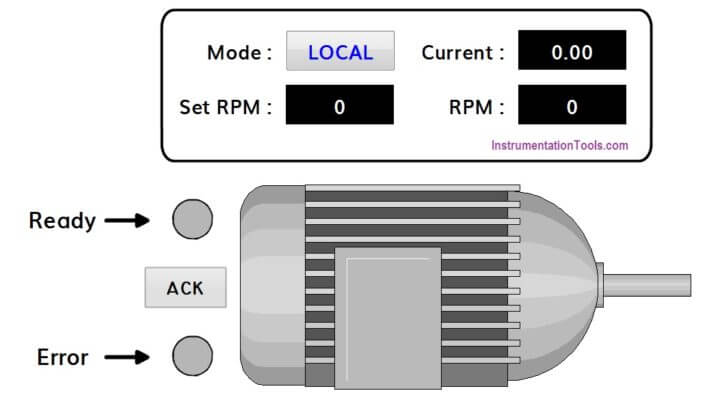
SCADA Normal State

This is the normal state of motor. There is no error as well as Ready bit is also in normal state.

Also the speed selection is in LOCAL mode.

Running State
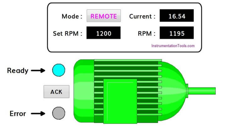
SCADA Running State

This state shows that Ready bit is high and motor is running without any error.

Error State
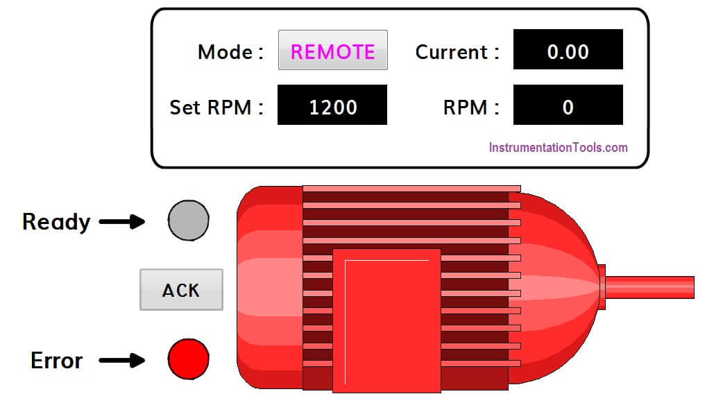
SCADA Error State

There is an error bit is high and motor also showing error condition.

Note :

In some industries, Yellow color also used to indicate the error condition. Red color is used to indicate motor stop condition.

Author : Hiral Patel

If you liked this article, then please subscribe to our YouTube Channel for PLC and SCADA video tutorials.

You can also follow us on Facebook and Twitter to receive daily updates.

Read Next:

PLC Logic for Oil Pump Motor

Car Washing using Ladder Logic

PLC Sequencer Programming

One Shot Falling Instructions

Ladder Logic for Tanks Filling
Don't Miss Our Updates
Be the first to get exclusive content straight to your email.
We promise not to spam you. You can unsubscribe at any time.
Invalid email address
You've successfully subscribed !

Continue Reading

What is Motor Jogging ?
Tia Portal – OB121 Programming Errors Interrupt Organization Block
Count and Pack Objects from Conveyor using PLC Ladder Logic
Edge Detection in PLC Programming
PLC Programming Example on Timers Function Block
What is Interface Module in Siemens PLC?
Share This Article
Facebook Whatsapp Whatsapp LinkedIn Copy Link
Share
7 Comments
  • Satish says:
    August 15, 2019 at 6:28 pm

    Good program

    Reply
  • tosif mansuri says:
    August 16, 2019 at 4:01 pm

    Good

    Reply
  • Jitendra nath nayak says:
    August 16, 2019 at 8:57 pm

    Communication btn drive & plc

    Reply
  • sridhar says:
    June 25, 2020 at 10:39 am

    nice explanation

    Reply
  • Suresh Kumar says:
    January 24, 2021 at 11:53 am

    Nice program logic

    Reply
  • biraj says:
    February 25, 2022 at 12:53 pm

    this is a great site, it would be more systematic if the course contents were shown from zero to advance

    Reply
  • Heybar Sequera says:
    January 29, 2023 at 2:15 am

    What do represent Temp1 and Tem2 on the Networks 2 & 3?
    Thanks in advance.

    Reply

Leave a Reply Cancel reply

Your email address will not be published. Required fields are marked *

Stay Connected

128.3kFollowersLike
69.1kFollowersFollow
210kSubscribersSubscribe
38kFollowersFollow

Categories

Explore More

PLC Program for Boolean Expression
Design a Water Pump PLC Program using CX-Programmer
PLC Program for Entry and Exit Control of Car Parking
PID in Studio 5000
One Shot Rising and One Shot Falling Instructions in PLC
Ladder Logic for Flow Meter Totalizer
Allen Bradley Math Functions
How to Troubleshoot a PLC System?

Keep Learning

Siemens PLC Write Protection

How to Protect Siemens PLC using Password?

JMP instruction in PLC Programming

How to use JUMP Instruction in PLC Ladder Logic?

How to Use Analog Input in Mitsubishi FX3U LOLLETTE PLC

How to Use Analog Input in Mitsubishi FX3U LOLLETTE PLC?

Converter Instruction in Siemens PLC Programming

Converter Instruction in Siemens PLC Programming

4-20mA Loop Power Supply Questions

4-20mA Loop Power Supply Questions and Answers

PLC Program Example - Signal Lamp Task

PLC Program Examples

Omron CX programmer shift register

The Concept of Shift Register in Omron PLC with Example

Siemens S7 300 and STEP 7 PLC program using SIMATIC Software

Learn More

Relay-Operation

Relay Working Animation

PIN Diode Working Principle

PIN Diode Working Principle

Difference between Repeatability and Reproducibility

Difference between Repeatability and Reproducibility

Electrical Heating Objective Questions and Answers

Electrical Heating Objective Questions and Answers

wash column temperature control

Pneumatic Instrumentation

DTMF Based Project Topics and Ideas

Top 100 DTMF Based Projects, Topics and Ideas

Difference between SIS, PLC and BPCS Systems

Difference between SIS, PLC and BPCS Systems

Gas-detection-system

Selection Criteria for Toxic Gas Detector

Menu

  • About
  • Privacy Policy
  • Copyright

Quick Links

  • Learn PLC
  • Helping Hand
  • Part Time Job

YouTube Subscribe

Follow US
All rights reserved. Reproduction in whole or in part without written permission is prohibited.
Welcome Back!

Sign in to your account

Username or Email Address
Password

Lost your password?