Inst ToolsInst ToolsInst Tools
  • Courses
  • Automation
    • PLC
    • Control System
    • Safety System
    • Communication
    • Fire & Gas System
  • Instrumentation
    • Design
    • Pressure
    • Temperature
    • Flow
    • Level
    • Vibration
    • Analyzer
    • Control Valve
    • Switch
    • Calibration
    • Erection & Commissioning
  • Interview
    • Instrumentation
    • Electrical
    • Electronics
    • Practical
  • Q&A
    • Instrumentation
    • Control System
    • Electrical
    • Electronics
    • Analog Electronics
    • Digital Electronics
    • Power Electronics
    • Microprocessor
  • Request
Search
  • Books
  • Software
  • Projects
  • Process
  • Tools
  • Basics
  • Formula
  • Power Plant
  • Root Cause Analysis
  • Electrical Basics
  • Animation
  • Standards
  • 4-20 mA Course
  • Siemens PLC Course
Reading: How to Calibrate Load Cells in Weighing Applications?
Share
Notification Show More
Font ResizerAa
Inst ToolsInst Tools
Font ResizerAa
  • Courses
  • Design
  • PLC
  • Interview
  • Control System
Search
  • Courses
  • Automation
    • PLC
    • Control System
    • Safety System
    • Communication
    • Fire & Gas System
  • Instrumentation
    • Design
    • Pressure
    • Temperature
    • Flow
    • Level
    • Vibration
    • Analyzer
    • Control Valve
    • Switch
    • Calibration
    • Erection & Commissioning
  • Interview
    • Instrumentation
    • Electrical
    • Electronics
    • Practical
  • Q&A
    • Instrumentation
    • Control System
    • Electrical
    • Electronics
    • Analog Electronics
    • Digital Electronics
    • Power Electronics
    • Microprocessor
  • Request
Follow US
All rights reserved. Reproduction in whole or in part without written permission is prohibited.
Inst Tools > Blog > Calibration > How to Calibrate Load Cells in Weighing Applications?

How to Calibrate Load Cells in Weighing Applications?

Last updated: November 14, 2019 3:27 pm
Editorial Staff
Calibration
4 Comments
Share
5 Min Read
SHARE

Load cells are special force transducers used for measuring weight or force in various applications. These are integral to weighing systems in various industries, including aerospace, marine, automotive. The reason being they produce highly accurate load measurement data. That is why it is essential to inspect and calibrate them routinely.

Contents
How to Calibrate Load CellsWhy You Should Calibrate Load CellsSteps to Calibrate Load Cells in Weighing ApplicationsBridge Resistance:Zero Balance:Resistance to Ground:

Weighing scale calibration services ensure accurate load cell readings and help identify operational issues so that negative consequences can be prevented.

How to Calibrate Load Cells

How to Calibrate Load Cells

Why You Should Calibrate Load Cells

Load cells show signs of wear and tear over a period of years. Frequency of use, environmental causes such as temperature, and aging are some of the contributing factors to the deterioration of load cells.

Faulty cables and instruments, particle accumulation and matter buildup, mechanical defects, incorrect installation, and the influence of electricity can also lead to inefficiency.

That is why routine calibrations should be performed to ensure the efficiency and accuracy of load cells. In the absence of frequent calibrations, load cells can give incorrect readings and produce erroneous data.

Routine calibration of load cells can help achieve accuracies of around 0.03 to 1%. As part of product liability, safety, and compliance in a Quality Management System, load cells are required to be calibrated to National standards.

Steps to Calibrate Load Cells in Weighing Applications

Before calibrating load cells, inspect whether the machine is giving correct measurement data.

We have mentioned three key indicators to evaluate whether the load cells and transducers are functioning correctly, these are:

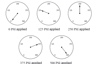
  • When the system is unloaded or empty, the weight indication should return to zero.
  • The indicated weight must be double when the weight is doubled.
  • Irrespective of where the load is placed, the weight indicator should give equal readings.

Provided that all the conditions are met, it is safe to conclude that the load cells and transducers are working.

If you notice otherwise, follow the next steps.

  • Load cells can give inaccurate readings due to faulty cables and incorrect installation. Therefore, check the following before calibrating load cells:
  • Inspect the electrical cables and wires
  • Remember to place dummy cells in place of operational load cells until construction and welding work is finished.

After performing the preliminary tests, if you find that load cells are causing problems, conduct the following tests:

Physical Inspection:

This involves inspection for any physical damage in the load cell. Also, check for dents and cracks on all sides.

Note that if the load cell is not in its original shape and is altered- compressed, bent, or stretched, you need to replace the cell.

Bridge Resistance:

This test should be done when there is no load and the system is disconnected from the weight controller. Now measure the excitation leads for input resistance, and signal leads for output resistance.

Compare the readings with the load cell specifications. out-of-tolerance readings are often caused by power fluctuation.

Zero Balance:

Residual stress in the sensing area can often cause a shift in zero balance. If a load cell is overloaded repeatedly over multiple operational cycles, residual stress builds up.

Check the output of a load cell with a voltmeter when the system is empty. It must be within 0.1% of the mentioned zero output signal. If it exceeds the zero balance tolerance band, the cell might be damaged.

Resistance to Ground:

Connect the input, output, and ground leads. With the help of an ohmmeter, check the resistance between the load cell body and the leads. If the reading does not reach 5,000 megaohms, separate the ground wire, and repeat the test. If it fails again, the cell could be damaged.

By following these steps, you would not only ensure load cells are functioning correctly but would also be able to prevent and take precautions against any potential damages.

Author Bio:

Kevin HillKevin Hill heads the marketing efforts at Quality Scales Unlimited in Byron, CA. Besides his day job, he loves to write about the different types of scales and their importance in various industries. He also writes about how to care for and get optimized performance from different scales in different situations. He enjoys spending time with family and going on camping trips.

Don't Miss Our Updates
Be the first to get exclusive content straight to your email.
We promise not to spam you. You can unsubscribe at any time.
Invalid email address
You've successfully subscribed !

Continue Reading

Self Actuated Pressure Control Valve Functional Testing
Stroke Checking Procedure for GCV, SRV, IGV, and LFBV
Fieldbus Flow Transmitter Configuration
Difference between Calibration and Ranging
History of Measurement
Instrument Turndown Ratio
Share This Article
Facebook Whatsapp Whatsapp LinkedIn Copy Link
Share
4 Comments
  • edshesolomon says:
    November 15, 2019 at 10:36 am

    you need to teach me by my email

    Reply
  • surender singh says:
    November 16, 2019 at 11:34 am

    Hello dear
    How can I apply for a job in Mettler Toledo

    Reply
  • Sharif says:
    December 20, 2019 at 7:23 pm

    Want to know about in RESOLVER & ENCODER, How it work, Testing, Commissioning etc….thanks

    Reply
  • Prakash Sharma says:
    May 20, 2024 at 5:34 pm

    Want to know about 4-wire and 6-wire Load cell.

    Reply

Leave a Reply Cancel reply

Your email address will not be published. Required fields are marked *

Stay Connected

128.3kFollowersLike
69.1kFollowersFollow
210kSubscribersSubscribe
38kFollowersFollow

Categories

Explore More

Pressure Safety Valve Leak Test Procedure (PSV Testing)
DP type Flow Transmitter Preventive Maintenance and Calibration
Control Valve Stroke Test Procedure
Types of Calibration
Ultrasonic Level Transmitter Principle, Limitations, Calibration and configuration
Open Tank DP Level Transmitter Calibration
List of Documents Required for Testing and Calibration Laboratories
DP Transmitter Interface Level Measurement Principle, Limitations, Selection, Installation, Design & Calibration

Keep Learning

Instrument Calibration Record

How to Create Calibration Records?

Thermocouple Calibration

Thermocouple Calibration

Pig Signalling Switches Functional Testing

Pig Signalling Switches Functional Testing

Open-Tank-DP-Level-Transmitter-with-Zero-Suppression-Calibration

DP Level Transmitter with Zero Suppression Calibration

Functional Testing of Control Valve Positioners

Functional Testing of Control Valve Positioners

pH Analyzer Calibration and Troubleshooting

pH Analyzer Calibration and Troubleshooting

Field Transmitter Damping

What is Field Transmitter Damping ?

Capacitance Level measurement principle

Capacitance Level Sensor Principle, Limitations, Installation & Calibration

Learn More

Transformer Open and Short Circuit Tests

vibration probe mounting

Mechanical Vibration Switch Principle

Analog Electronics Objective Questions

Analog Electronics Objective Questions – Set 2

Voltage Polarities

Voltage Polarity and Current Direction

What is a Line Choke or Reactor in a VFD

What is a Line Choke or Reactor in a VFD?

Parts of the Temperature Calibrator

What is a Dry Block? – Parts of the Temperature Calibrator

Can a PLC Function Without an HMI or SCADA

Can a PLC Function Without an HMI or SCADA?

Level Transmitter configuration in PLC

Scaling with Parameters (SCP) Instruction in PLC

Menu

  • About
  • Privacy Policy
  • Copyright

Quick Links

  • Learn PLC
  • Helping Hand
  • Part Time Job

YouTube Subscribe

Follow US
All rights reserved. Reproduction in whole or in part without written permission is prohibited.
Welcome Back!

Sign in to your account

Username or Email Address
Password

Lost your password?