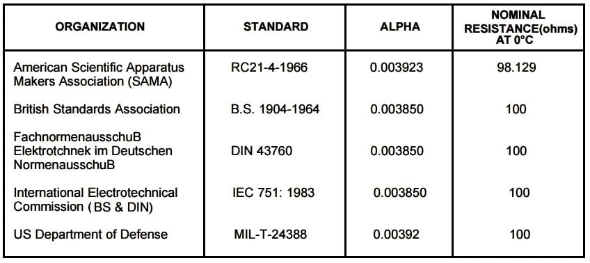
The European standard, also known as the DIN or IEC standard, is considered the world-wide standard for Pt100. This standard, DIN/IEC 60751 (or simply IEC751), requires the RTD to have an electrical resistance of 100.00 Ω at 0°C and a temperature coefficient of resistance (alpha) of 0.00385 Ω/Ω/°C between 0 and 100°C.

There are actually four resistance tolerances specified in DIN/IEC751:2008
Class AA = ± ( 0.10 + 0.0017 * | t | ) °C
Class A = ± ( 0.15 + 0.0020 * | t | ) °C
Class B = ± ( 0.30 + 0.0050 * | t | ) °C
Class C = ± ( 0.60 + 0.0100 * | t | ) °C
The combination of resistance tolerance and temperature coefficient define the resistance vs. temperature characteristics for the RTD sensor. The larger the element tolerance, the more the sensor will deviate from a generalized curve, and the more variation there will be from sensor to sensor (interchangeability). This is important for users who need to change or replace sensors and want to minimize interchangeability errors.
Tolerance Testing Method
RTD calibrations involving tolerance testing are reserved for low accuracy applications. The values are defined by one of the common models such as the ASTM 1137 or IEC 60751 curve. RTDs calibrated in this way are generally used in industrial style applications
The two common accuracy classes are class A and class B:
These include errors arising from deviations in R0 and from errors in slope. Frequently, we will see probes rated at a fraction of Class A.
For example, 0.1 ASTM Class A. Fractional accuracy is achievable in sensors alone, but are very difficult to achieve in probes. The calculations are straightforward.
Example: Calculate the accuracy of a 0.1 ASTM Class A probe at 100 °C
For ASTM standard:
Class A = ± [0.13 + (0.0017 · t)] °C
= (0.13 + (0.0017 · t)) · 0.1
= (0.13 + (0.0017 · 100)) · 0.1
= (0.13 + 0.17) · 0.1
= 0.03
Measure the reference probe temperature = 100.0 °C
Measure the indicated temperature = 100.5 °C
Calculate the error (Difference of Indicated & Reference) = 0.05 °C
Calculate the tolerance at 100.00 °C using ASTM standard = 0.03 °C
Determine tolerance status = Fail (0.05 °C > 0.03 °C)
The above example calculates the RTD tolerance at reference and indicated temperatures and determines the tolerance status of an RTD.
PLC ladder logic design to control 3 motors with toggle switch and explain the program…
VFD simulator download: Master the online tool from the Yaskawa V1000 & programming software for…
The conveyor sorting machine is widely used in the packing industries using the PLC program…
Learn the example of flip-flop PLC program for lamps application using the ladder logic to…
In this article, you will learn the STAR DELTA programming using PLC controller to start…
Lube oil consoles of rotary equipment packages in industrial process plants are usually equipped with…
View Comments
Hi,
This is a nice explanation. Can you make a tool for RTD tolerance calculation.
Regards,
Giri
Hi Giri,
Thanks for the suggestion. Soon i will post a tool on RTD tolerance.
Thanks,
S Bharadwaj reddy
Hi Guys...!
Its very good information we all appreciate to Mr Reddy to serve and share with us..