Inst ToolsInst ToolsInst Tools
  • Courses
  • Automation
    • PLC
    • Control System
    • Safety System
    • Communication
    • Fire & Gas System
  • Instrumentation
    • Design
    • Pressure
    • Temperature
    • Flow
    • Level
    • Vibration
    • Analyzer
    • Control Valve
    • Switch
    • Calibration
    • Erection & Commissioning
  • Interview
    • Instrumentation
    • Electrical
    • Electronics
    • Practical
  • Q&A
    • Instrumentation
    • Control System
    • Electrical
    • Electronics
    • Analog Electronics
    • Digital Electronics
    • Power Electronics
    • Microprocessor
  • Request
Search
  • Books
  • Software
  • Projects
  • Process
  • Tools
  • Basics
  • Formula
  • Power Plant
  • Root Cause Analysis
  • Electrical Basics
  • Animation
  • Standards
  • 4-20 mA Course
  • Siemens PLC Course
Reading: History of 3-15 psi, 10-50 mA, and 4-20 mA signals
Share
Font ResizerAa
Inst ToolsInst Tools
Font ResizerAa
  • Courses
  • Design
  • PLC
  • Interview
  • Control System
Search
  • Courses
  • Automation
    • PLC
    • Control System
    • Safety System
    • Communication
    • Fire & Gas System
  • Instrumentation
    • Design
    • Pressure
    • Temperature
    • Flow
    • Level
    • Vibration
    • Analyzer
    • Control Valve
    • Switch
    • Calibration
    • Erection & Commissioning
  • Interview
    • Instrumentation
    • Electrical
    • Electronics
    • Practical
  • Q&A
    • Instrumentation
    • Control System
    • Electrical
    • Electronics
    • Analog Electronics
    • Digital Electronics
    • Power Electronics
    • Microprocessor
  • Request
Follow US
All rights reserved. Reproduction in whole or in part without written permission is prohibited.
Inst Tools > Blog > Instrumentation Design > History of 3-15 psi, 10-50 mA, and 4-20 mA signals

History of 3-15 psi, 10-50 mA, and 4-20 mA signals

Study about the history of 4-20 mA signals used in the industrial instrumentation. Other signals are 3-15 psi, and 10-50 mA

Last updated: September 19, 2020 5:37 pm
Editorial Staff
Instrumentation Design
1 Comment
Share
2 Min Read
SHARE

Before 4-20 mA the signals were 3-15 psi and 10-50 mA. These signals all have a ā€œlive zeroā€ (3 psi, 10 mA, and 4 mA) rather than a ā€œdead zeroā€ (0 psi, 0 mA) which can be used to detect a severed pneumatic tube or signal wire.

Contents
3-15 psi Pneumatic Signal10-50 mA Analog Electronic Signal4-20 mA Analog Electronic Signal

The live zero can also be used to power a 2-wire loop-powered device. 3-15 psi, 10- 50 mA, and 4-20 mA etc. all have a ratio of 1:5 (20% bias).

History of 3-15 psi, 10-50 mA, and 4-20 mA signals

Nobody remembers the exact reason why the signal ranges 3-15 psi, 10-50 mA, and 4-20 mA were selected and there appears to be no definite source documenting this decision such as minutes of meeting from a standards committee.

Some research has uncovered the following technical reasons why these signal ranges were chosen.

3-15 psi Pneumatic Signal

Pneumatic instruments operate on the flapper-nozzle (baffle-nozzle) principle. It appears 3-15 psi with the 1:5 ratio was chosen because it the most linear portion on the curve for the movement of the flapper (baffle) and the backpressure resulting in the nozzle.

10-50 mA Analog Electronic Signal

Early analog electronic instruments used magnetic amplifiers. 10 mA live zero was chosen as it is the lowest at which instrument based on magnetic amplifiers could operate. Maintaining the 1:5 ratio the signal was chosen 10-50 mA.

4-20 mA Analog Electronic Signal

With the introduction of the transistor, it became possible to make devices operating on 4 mA. Thus the signal was chosen 4-20 mA maintaining the 1:5 ratio. With the introduction of microprocessors in instrumentation and digital communication, the HART protocol was introduced superimposed over the 4-20 mA signal.

The HART commands supported by the device, how device information is displayed, and the wizards to make tasks like calibration easy, etc.

Also, Click here to read the advantages of the 4-20mA signal.

Source: Eddl.Org

Don't Miss Our Updates
Be the first to get exclusive content straight to your email.
We promise not to spam you. You can unsubscribe at any time.
Invalid email address
You've successfully subscribed !

Continue Reading

Package Control and Safety Systems Implementation Methods
How to Select a Rotameter? – Parameters and Applications
Orifice Sizing Guidelines and Thumb Rules with Flowchart
Pneumatic Valves and Cylinders Sizing – Part 1
Difference between DCS & PLC Systems
Pressure Control Valves vs Pressure Regulators
Share This Article
Facebook Whatsapp Whatsapp LinkedIn Copy Link
Share
1 Comment
  • dan says:
    May 14, 2017 at 6:57 am

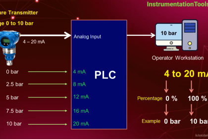
    Why we use a standard of 4-20 mA ?

    A 4-10mA corresponds to a 1-5V analog voltage across a 250 Ohm resistor, making it easy to adapt the 4-20mA current loop to a 1-5VDC analog input voltage (common on many controllers using TTL inputs) to by simply placing a 250 Ohm resistor across the analog input terminals of the controller.

    The industry specification for Compatibility of Analog Signal for Electronic Industrial Process Instruments is ISA 50.00.01-1975 (R2012). The pre-1972 version of this standard specified 10-50mA for analog current loops because the technology at the time used magnetic amplifiers which required a minimum of 10mA to operate.

    Since transistor circuits have become more stable and accurate, the 4-20mA analog current loop has become the standard, requiring less power and allowing greater distances.

    Of course, if you aren’t already aware, one of the main advantages of current loop over voltage driven analogue signals is that a current driven loop allows greater distances to be achieved – typically lengths up to 1000m are possible.

    Any signal sent over a long distance produces a voltage drop which is in proportion to the length of the cable (cable resistance), however when a 4-20mA signal is used to transmit the analog signal (as opposed to a 1-5VDC signal), the voltage drop is irrelevant, since the same current has to pass through the circuit loop (it has no where else to go!) provided the power supply can handle it. For example, for a 24VDC powered transmitters, 7-15VDC is typically used by the transmitter circuit, leaving a budget of at least 9VDC for the loop voltage drop.

    You may already be aware that having a non-zero current (4mA) for representing the “zero value” of the analog signal allows the controller to detect a broken wire (0mA) as well as allowing loop-powered transmitter design.

    Having the 20mA correspond to the ‘maximum value’ of the analog signal is practical for industrial process instruments, since having larger currents would result in larger voltage drop for the same size cabling, thereby limiting the cable length.

    Also, limiting the power of signals in the transmitter is better for ‘intrinsically safe design’ by limiting the energy available for igniting explosive dust or vapors in hazardous areas (as per ANSI/ISA-RP12.06.01-2003 Recommended Practice for Wiring Methods for Hazardous (Classified) Locations Instrumentation Part 1: Intrinsic Safety).

    Source : stackexchange

    Reply

Leave a Reply Cancel reply

Your email address will not be published. Required fields are marked *

Stay Connected

128.3kFollowersLike
69.1kFollowersFollow
210kSubscribersSubscribe
38kFollowersFollow

Categories

Explore More

Pressure Gauge Problems
Safety Instrumented System Module Failure
What is SAMA Diagram?
Control Room Design Guidelines
System Architecture and Process Control Systems Philosophy
Readings Mismatch between Field & Control Room ? Why
How to Calculate Heat Load in Electrical/Electronic Panel Enclosure
What is Nest Loading? – DCS and PLC Control Systems

Keep Learning

Cable Tray Routing

Cable Routing

Relay Circuit for Hooter with Reset Button

Relay Latching Circuit using Push Button

Remote Seals Transmitters Temperature Error

Remote Seal Transmitters Temperature Error

Fail Safe Switch Circuit

Basics of Fail-safe Circuits

pressure switch control two lamps wiring

Draw Wiring of a Pressure Switch to control two lamps

Axial Diaphragm Seal Connection

Difference between Axial and Radial Diaphragm Seal Connection?

Failsafe interlock Design

Failsafe Wiring Practices

Instrumentation During the Detail Design Phase

Instrumentation Engineer Activities & Documents – Detail Design Phase

Learn More

Turbine Flow Meter (TFM) Field Calibration

Turbine Flow Meter (TFM) Field Calibration Uncommon Request

Water Vapor in Instrument Air Lines

How to Minimize Water Vapor in Instrument Air Lines?

Differential Pressure Sensor with pair of Strain Gauges

Differential Pressure Sensor with Pair of Strain Gauges

Strain Gauge Pressure Sensor Principle

Strain Gauge Pressure Sensor Principle

TOC Analyzer Principle

Total Organic Carbon Analyzer Principle

Demister Pads Problem

Problems with Demister Pads – Root Cause Analysis (RCA)

Electromagnetic Flow Meters Working Principle

11 kV, 3.3 kV, and 400 V systems insulation resistance (IR) Problems

11 kV, 3.3 kV, and 400 V systems insulation resistance (IR) Problems

Menu

  • About
  • Privacy Policy
  • Copyright

Quick Links

  • Learn PLC
  • Helping Hand
  • Part Time Job

YouTube Subscribe

Follow US
All rights reserved. Reproduction in whole or in part without written permission is prohibited.
Welcome Back!

Sign in to your account

Username or Email Address
Password

Lost your password?