Voltage multipliers use clamping action to increase peak rectified voltages without the necessity of increasing the transformer’s voltage rating. Multiplication factors of two, three, and four are common. Voltage multipliers are used in high-voltage, low-current applications such as cathode-ray tubes (CRTs) and particle accelerators.
Voltage Doubler
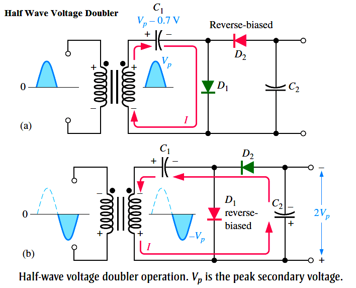
Half Wave Voltage Doubler
A voltage doubler is a voltage multiplier with a multiplication factor of two. A half-wave voltage doubler is shown in Below Figure. During the positive half-cycle of the secondary voltage, diode D1 is forward-biased and D2 is reverse-biased. Capacitor C1 is charged to the peak of the secondary voltage (Vp) less the diode drop with the polarity shown in part (a). During the negative half-cycle, diode D2 is forward-biased and D1 is reverse-biased, as shown in part (b). Since C1 can’t discharge, the peak voltage on C1 adds to the secondary voltage to charge C2 to approximately 2Vp. Applying Kirchhoff’s law around the loop as shown in part (b), the voltage across C2 is
VC1 – VC2 + Vp = 0
VC2 = Vp + VC1
Neglecting the diode drop of D2, VC1 = Vp. Therefore,
VC2 = Vp + Vp = 2Vp
Under a no-load condition, C2 remains charged to approximately 2Vp. If a load resistance is connected across the output, C2 discharges slightly through the load on the next positive half-cycle and is again recharged to 2Vp on the following negative half-cycle. The resulting output is a half-wave, capacitor-filtered voltage. The peak inverse voltage across each diode is 2Vp. If the diode were reversed, the output voltage across C2 would have the opposite polarity.