How to Create a user-defined Function Block (FB) for Motor Control Logic in Programmable Logic Controllers (PLC).
Function Block Motor Logic
There is one industrial motor and we need to control with FB block logic. Also, consider all interlock like a trip signal, maintenance, etc. Write the PLC program for this logic and configuration.
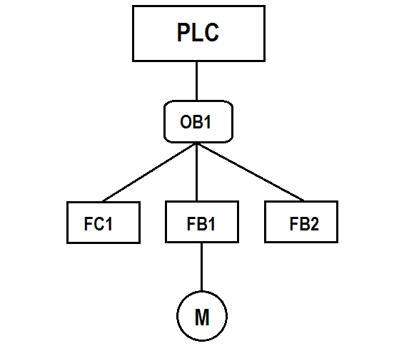
For this example, we will use the Function block (FB) for motor control logic. Normally START and STOP buttons are used for motor control.
With FBs, the input, output, in/out, and static variables are saved in the instance DB specified in the call statement. The temporary variables are stored in the L stack.
Function block (FB) logic is used for multiple logic applications. For example, there are two industrial motors in the application. Both the motors are operated in the same logic independently. So we will write logic in FB block for one motor function and use the same for other motors as well. (call FB 1 and FB 2 in OB 1).
List of Inputs:-
- I0.0:- Industrial Motor 1 Start
- I0.1:- Industrial Motor 1 Stop
- I0.2:- Industrial Motor 1 Trip
- I0.3: Maintenance lamp Reset
List of Outputs:-
- Q0.0:- Industrial Motor On
- Q0.1:- Fault lamp
- Q0.2:- Maintenance lamp
Memory:-
- M0.0:- Motor on command
- MW10:- Counter value
OB1:-
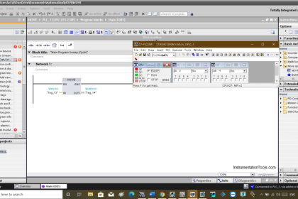
Organization block for industrial motor 1 logic. FB 1 is called in OB 1.
Here we are using FB1 block only for one motor control. Generally, FB blocks can be called multiple times in a logic depends on the number of motors to control.
If there are more motors in the application, FB 1 can be called for other motors also, no need to write logic every time.
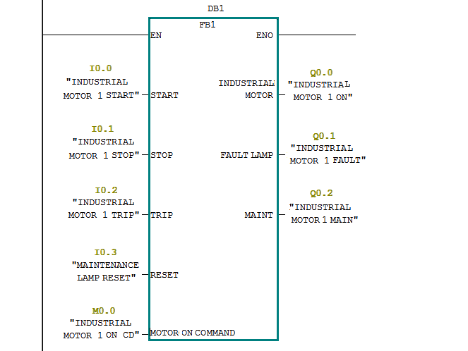
Function Block (FB1):-
Function block for logic. In this block, we have declared all temporary variables for motor logic.
The below-shown ladder logic will be added in our function block FB1, so every time when you call the function block (FB1), it will perform the function as written in the ladder logic.
You can also compare the inputs & outputs labels in the function block (FB1)with respect to the below ladder logic. The function block (FB1) will have the function, inputs, outputs based on this ladder logic only.
Network 1:-
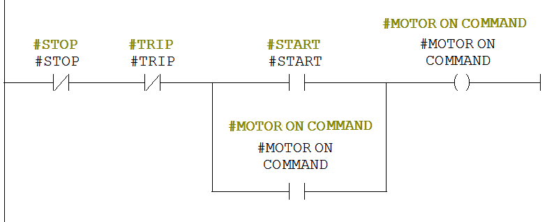
In this network, motor START/STOP logic is used as per normal motor control logic.
Motor 1 can be started by pressing the START BUTTON (I0.0) and sopped by pressing STOP PB (I0.1).
If trip input (I0.2) triggered, motor ON command (M0.0) will be OFF and motor will be stopped.
Network 2:-
When motor command ON, industrial motor (Q0.0) will be ON (Started).

Network 3:-
If the Trip command (I0.3) is activated, the fault lamp (Q0.1) will be ON.

Network 4:-
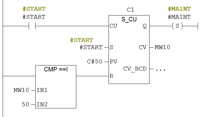
In this network, counter logic is used for a maintenance lamp. If START BUTTON (I0.0) is pressed for 50 times, the maintenance lamp (Q0.2) will be ON. The counter will be reset after 50 counts.
Network 5:-
The maintenance lamp (Q0.2) can be reset by pressing MAINTENANCE RESET BUTTON (I0.4).

As the above explanation, you can write the logic for other motors also. Call FB in OB1 for the second motor and configure the inputs and outputs.
Note:- This is the simple example for FB function used for motor logic in PLC, we can use this concept in other examples also.
If you liked this article, then please subscribe to our YouTube Channel for PLC and SCADA video tutorials.
You can also follow us on Facebook and Twitter to receive daily updates.
Read Next:
Fieldbus Logic and Configuration



Dear Sir,
Thanks for your wonderful article. There should be a Print button for Printing in a proper Format so that Printout can be taken .
If we take printout many unwanted ads , No proper formatting comes.
Plz look into the suggestion if feasible.
this is wrong program . the counter will not count up to 50 , cuz every time you press the start switch mw10 will store directly 50 and it will reset the counter again .