Inst ToolsInst ToolsInst Tools
  • Courses
  • Automation
    • PLC
    • Control System
    • Safety System
    • Communication
    • Fire & Gas System
  • Instrumentation
    • Design
    • Pressure
    • Temperature
    • Flow
    • Level
    • Vibration
    • Analyzer
    • Control Valve
    • Switch
    • Calibration
    • Erection & Commissioning
  • Interview
    • Instrumentation
    • Electrical
    • Electronics
    • Practical
  • Q&A
    • Instrumentation
    • Control System
    • Electrical
    • Electronics
    • Analog Electronics
    • Digital Electronics
    • Power Electronics
    • Microprocessor
  • Request
Search
  • Books
  • Software
  • Projects
  • Process
  • Tools
  • Basics
  • Formula
  • Power Plant
  • Root Cause Analysis
  • Electrical Basics
  • Animation
  • Standards
  • 4-20 mA Course
  • Siemens PLC Course
Reading: Full Wave Bridge Rectifier Peak Inverse Voltage
Share
Font ResizerAa
Inst ToolsInst Tools
Font ResizerAa
  • Courses
  • Design
  • PLC
  • Interview
  • Control System
Search
  • Courses
  • Automation
    • PLC
    • Control System
    • Safety System
    • Communication
    • Fire & Gas System
  • Instrumentation
    • Design
    • Pressure
    • Temperature
    • Flow
    • Level
    • Vibration
    • Analyzer
    • Control Valve
    • Switch
    • Calibration
    • Erection & Commissioning
  • Interview
    • Instrumentation
    • Electrical
    • Electronics
    • Practical
  • Q&A
    • Instrumentation
    • Control System
    • Electrical
    • Electronics
    • Analog Electronics
    • Digital Electronics
    • Power Electronics
    • Microprocessor
  • Request
Follow US
All rights reserved. Reproduction in whole or in part without written permission is prohibited.
Inst Tools > Blog > Electronic Devices & Circuits > Full Wave Bridge Rectifier Peak Inverse Voltage

Full Wave Bridge Rectifier Peak Inverse Voltage

Last updated: October 5, 2016 12:27 pm
Editorial Staff
Electronic Devices & Circuits
1 Comment
Share
1 Min Read
SHARE

Peak Inverse Voltage Let’s assume that D1 and D2 are forward-biased and examine the reverse voltage across D3 and D4. Visualizing D1 and D2 as shorts (ideal model), as in Figure (a), you can see that D3 and D4 have a peak inverse voltage equal to the peak secondary voltage. Since the output voltage is ideally equal to the secondary voltage,

PIV = Vp(out)

If the diode drops of the forward-biased diodes are included as shown in Figure (b), the peak inverse voltage across each reverse-biased diode in terms of Vp(out) is

Full Wave Rectifier Peak Inverse Voltage

The PIV rating of the bridge diodes is less than that required for the center-tapped configuration. If the diode drop is neglected, the bridge rectifier requires diodes with half the PIV rating of those in a center-tapped rectifier for the same output voltage.

Full Wave Rectifier Peak Inverse Voltage

Full Wave Rectifier Peak Inverse Voltage Formula

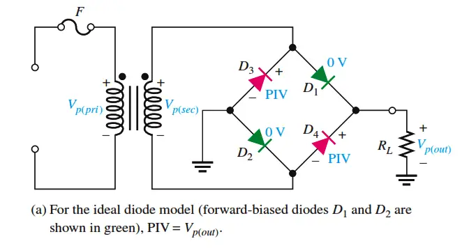
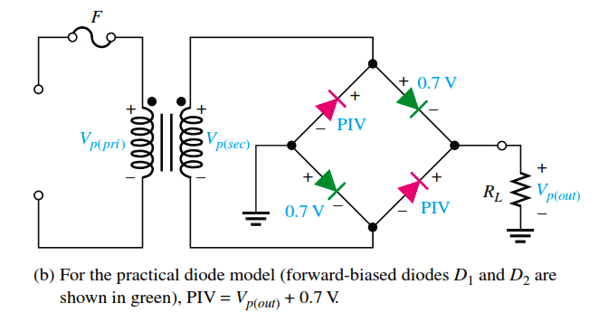
Fig : Peak inverse voltages across diodes D3 and D4 in a bridge rectifier during the positive half-cycle of the secondary voltage.

Don't Miss Our Updates
Be the first to get exclusive content straight to your email.
We promise not to spam you. You can unsubscribe at any time.
Invalid email address
You've successfully subscribed !

Continue Reading

Choke Input Filter Operation
Shockley Diode Working Principle
Zener Diode Limiter
Varactor Diode Operation
Cathode Ray Tube Deflection System
Forward Bias & Reverse Bias Diode Working Animation
Share This Article
Facebook Whatsapp Whatsapp LinkedIn Copy Link
Share
1 Comment
  • Azanlerigo Adewbowy says:
    July 14, 2024 at 7:51 pm

    You people really help solve my issue

    Reply

Leave a Reply Cancel reply

Your email address will not be published. Required fields are marked *

Stay Connected

128.3kFollowersLike
69.1kFollowersFollow
210kSubscribersSubscribe
38kFollowersFollow

Categories

Explore More

Diodes Voltage Quadrupler
Types of Resistors
Comparison of Half wave Rectifiers and Full wave Rectifiers
Voltage Divider Rule
Transistor as an Amplifier in Common Emitter
Limitations of Resistors
Applications of Photo diodes
Laser Diode Working Principle

Keep Learning

Derivation-of-Ohms-Law

Basics of Ohm’s Law

Current Limiting Resistor

Resistors Principle & Applications

zener-diode-as-voltage-regulator

Operation of Zener Diode Voltage Regulator

Dependent Current Source

Dependent Current Source

Transistor Stabilisation

Transistor Stabilisation

Electronic Symbols List

Electronic Symbols

Transistor Load Line Analysis

Transistor Load Line Analysis

Types-of-diodes

Different Types of Diodes

Learn More

Installation Precautions of Thermocouple and RTD

Installation Precautions of Thermocouple and RTD

PLC Program for Fishpond Water Level Monitoring System

PLC Program for Artificial Fishpond Water Level Monitoring System

Perfume filling system PLC program

CX Programmer Example: Perfume Mixing and Filling System

Direct Acting Solenoid Valve

Top 5 Things for selecting a Solenoid Valve

Architecture of Allen Bradley PLC

Architecture of Allen Bradley PLC

Sutro weir flow meter principle

Weirs and Flumes Flow Measurement

Control Systems Questions & Answers

Control Systems Objective Questions & Answers – Set 7

Power Electronics Objective Questions

Single-Phase Half Wave AC-DC Converter Objective Questions

Menu

  • About
  • Privacy Policy
  • Copyright

Quick Links

  • Learn PLC
  • Helping Hand
  • Part Time Job

YouTube Subscribe

Follow US
All rights reserved. Reproduction in whole or in part without written permission is prohibited.
Welcome Back!

Sign in to your account

Username or Email Address
Password

Lost your password?