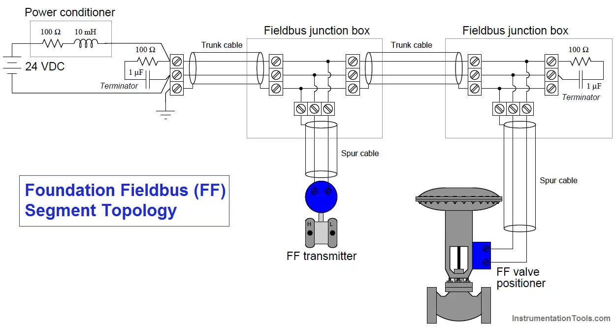
A minimal FF H1 segment consists of a DC power supply, a “power conditioner,” exactly two terminator resistors (Note 1) (one at each extreme end of the cable), a shielded and twisted-pair cable, and of course at least two FF instruments to communicate with each other.
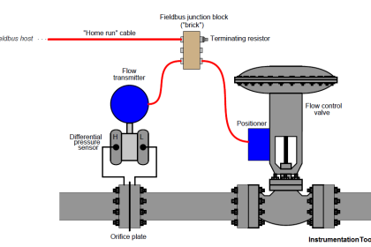
The cable connecting each instrument to the nearest junction is called a spur (or sometimes a stub or a drop), while the cable connecting all junctions to the main power source (where a host DCS would typically be located) is called a trunk (or sometimes a home run for the section leading directly to a host system):
Note 1 : Each FF terminator resistor is actually a series resistor/capacitor network. The capacitor blocks direct current, so that the 100 resistor does not impose a DC load on the system. The substantial current that would be drawn by a 100 ohm resistor across 24 VDC source if not blocked by a series capacitor (24 V / 100 ohms = 240 mA) would not only waste power (nearly 6 watts per resistor!) but that much current would cause an unnecessary degradation of supply voltage at the field device terminals due to voltage drop along the length of the segment cable’s conductors.
Foundation Fieldbus Topology
The power conditioner shown in this diagram is a simplified model of the actual device, the function of which being to filter out digital data pulses from reaching the DC power supply. Commercially-available Fieldbus power conditioners are complex electronic circuits rather than passive filter networks.
Normally, we would find more than two FF devices connected to a trunk cable, as well as a “host” system such as a DCS FF card for accessing FF instrument data, performing maintenance tasks, and integrating with other control loops.
Regardless of how many (or how few) FF devices connect to an H1 segment, though, there should always be exactly two terminating resistors in each segment – one at each end (Note 2) of the trunk cable. These resistor/capacitor networks serve the sole purpose of eliminating signal reflections off the ends of the trunk cable, making the cable look infinitely long from the perspective of the propagating pulse signals.
Missing terminators will result in signal reflections off the unterminated line end(s), while extra terminators have the equally deleterious effect of attenuating signal strength (as well as potentially causing signal reflections of opposite phase).
Note 2 : Be sure to check the specifications of the host system H1 interface card, because many are equipped with internal terminating resistors given the expectation that the host system will connect to one far end of the trunk!
All H1 networks are essentially parallel electrical circuits, where the two connection terminals of each field instrument are paralleled to each other. The physical arrangement of these transmitters, though, may vary substantially.
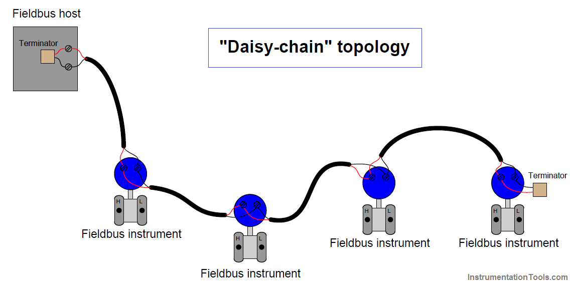
The simplest way to connect FF H1 devices together is the so called “daisy-chain” method, where each instrument connects to two cable lengths, forming an uninterrupted “chain” network from one end of the segment to the other:
Fieldbus Daisy-Chain Topology
As simple as this topology is, it suffers from a major disadvantage: it is impossible to disconnect any device in the segment without interrupting the network’s continuity.
Disconnecting (and reconnecting for that matter) any device necessarily results in all “downstream” devices losing signal, if only for a brief time. This is an unacceptable liability in most industrial applications, as it complicates maintenance and servicing of individual instruments on the segment.
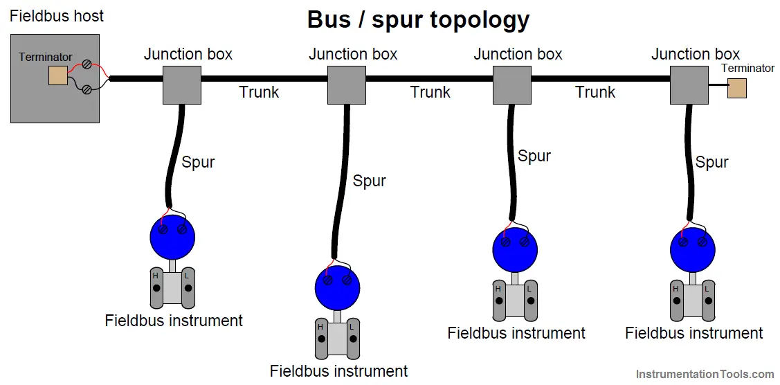
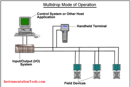
An alternative topology is the bus layout, where short “spur” cables connect instruments to a longer “trunk” cable.
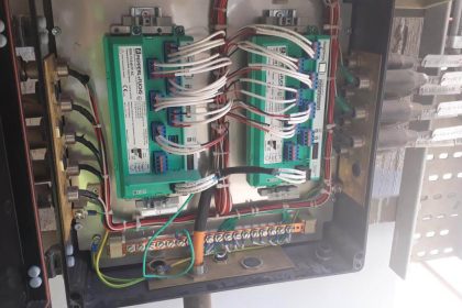
Terminal blocks – or even quick-disconnect couplings – within each junction box provide a convenient means of disconnecting individual devices from the segment without interrupting data communication with the other devices:
Fieldbus Bus Topology
The ideal arrangement for a “bus” network is to minimize the length of each spur cable, so as to minimize the delay of reflected signals off the unterminated ends of the drops. Remember that only two termination resistors are allowed in any electrically continuous network segment, and so this rule forbids the addition of terminators to the end of each spur cable.
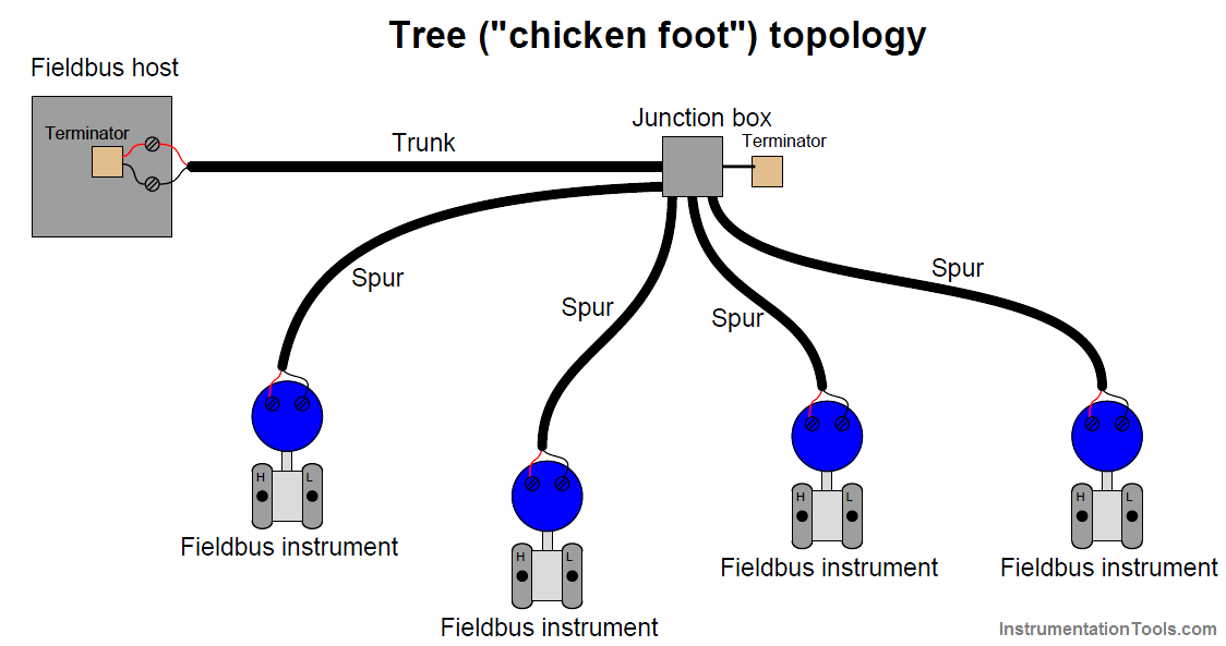
Yet another alternative topology for H1 networks is the so-called chicken-foot arrangement, where a long trunk cable terminates at a multi-point junction along with several field devices and their spur cables:
Fieldbus Tree Topology
Most FF systems resemble a combination of “bus” and “chicken-foot” topologies, where multiple junction devices serve as connection points for two or more field instruments per junction.











Tx bro..
Pleash tel me bro..
FF out put