By using this site, you agree to the Privacy Policy and Terms of Use.
Accept
Inst ToolsInst ToolsInst Tools
  • Ask
  • Courses
  • Videos
  • Q & A
    • Interview
      • Instrumentation
      • Electronics
      • Electrical
      • Practical Questions
    • MCQ
      • Instrumentation MCQ
      • Electrical MCQ
      • Electronics MCQ
      • Control Systems MCQ
      • Analog Electronics MCQ
      • Digital Electronics MCQ
      • Power Electronics MCQ
      • Microprocessor MCQ
      • Multiple Choice Questions
  • EE
    • Electronics
      • Electronics Q & A
      • Electronic Basics
      • Electronic Devices & Circuits
      • Electronics Animation
      • Digital Electronics
    • Electrical
      • Electrical Basics
      • Electrical Q & A
      • Power Electronics
      • Electrical Machines
      • Electrical Animation
      • Power Systems
      • Switchgear & Protection
      • Transmission & Distribution
  • Measure
    • Control Valves
    • Calibration
    • Temperature
    • Pressure
    • Flow
    • Level
    • Analyzers
    • Switches
    • Vibration
    • Solenoid Valve
  • Control
    • PLC Tutorials
    • Control Systems
    • Safety Instrumented System (SIS)
    • Communication
    • Fire & Gas System
  • More
    • Design
    • Tools
    • Animation
    • Basics
    • Formulas
    • Standards
    • TextBooks
    • Common
    • Software
    • Excel Tools
    • Erection & Commissioning
    • Process Fundamentals
    • Videos
    • Books
Search
All rights reserved. Reproduction in whole or in part without written permission is prohibited.
Reading: Foundation Fieldbus Electrical Parameters
Share
Notification Show More
Font ResizerAa
Inst ToolsInst Tools
Font ResizerAa
  • Ask
  • Courses
  • Videos
  • Q & A
  • EE
  • Measure
  • Control
  • More
Search
  • Ask
  • Courses
  • Videos
  • Q & A
    • Interview
    • MCQ
  • EE
    • Electronics
    • Electrical
  • Measure
    • Control Valves
    • Calibration
    • Temperature
    • Pressure
    • Flow
    • Level
    • Analyzers
    • Switches
    • Vibration
    • Solenoid Valve
  • Control
    • PLC Tutorials
    • Control Systems
    • Safety Instrumented System (SIS)
    • Communication
    • Fire & Gas System
  • More
    • Design
    • Tools
    • Animation
    • Basics
    • Formulas
    • Standards
    • TextBooks
    • Common
    • Software
    • Excel Tools
    • Erection & Commissioning
    • Process Fundamentals
    • Videos
    • Books
Follow US
All rights reserved. Reproduction in whole or in part without written permission is prohibited.
Inst Tools > Blog > Communication > Foundation Fieldbus Electrical Parameters

Foundation Fieldbus Electrical Parameters

Last updated: March 26, 2018 5:49 am
Editorial Staff
Communication
No Comments
Share
3 Min Read
SHARE

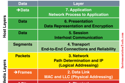
FOUNDATION Fieldbus H1 networks use Manchester encoding to represent bit states: a “high-to low” transition represents a logical zero (0), while a “low-to-high” transition represents a logical one (1). The following illustration shows how the data stream 00100 would be represented in Manchester encoding:

Manchester encoding

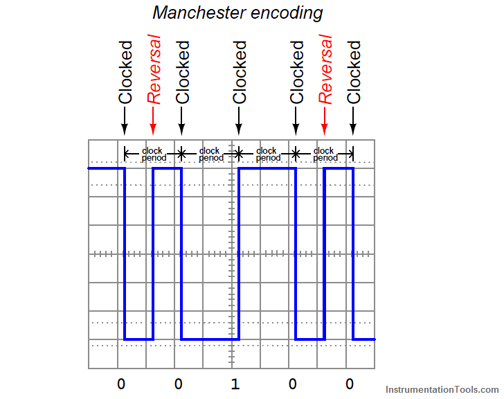
FF devices must be able to correctly distinguish between rising- and fall-edge signals in order to properly interpret the bit states of a Manchester-encoded signal. Any device interpreting these pulse edges “backwards” will invert every single bit! Thankfully, this problem is easy to avoid because the DC power supplied by the H1 segment wiring provides a “key” to identifying which wire is which, and therefore which pulses are rising-edge versus which pulses are falling-edge. For this reason, many (but not all!) FF devices are polarity-insensitive, automatically detecting the polarity of the network segment and compensating accordingly.

Every FF device draws at least 10 mA of current from the segment, and this current does not vary in the same manner that an analog (4-20 mA) device draws differing amounts of current under different operating conditions. Always remember that a Fieldbus device signals its variable(s) digitally, not by varying current. Old habits (and thought patterns) die hard, and so Fieldbus systems present challenges to technicians familiar with the behavior of analog current loop instrumentation. The amount of current drawn by any particular FF device depends on that device’s functionality – obviously, some will require more current for their operation than others. 10 mA to 30 mA should be considered a general range of current drawn by each FF device.

The standard operating voltage range for FF devices is between 9 and 32 volts DC. It is important to note, however, that not all manufacturers’ devices are in full compliance with the Fieldbus Foundation standard, and as such some may not operate properly at low voltages (near 9 volts DC)! The most common DC operating voltage for a FF network segment is 24 VDC (typical).

The minimum transmission voltage of a FF device is 750 millivolts peak-to-peak, while the minimum signal level for reception by a FF device is 150 millivolts peak-to-peak. This represents an acceptable attenuation of 5:1, or −14 dB between any two devices.

Don't Miss Our Updates
Be the first to get exclusive content straight to your email.
We promise not to spam you. You can unsubscribe at any time.
Invalid email address
You've successfully subscribed !
Foundation Fieldbus Device addressing
Difference Between Optical Fibre and Coaxial Cable
OTDR Testing
Network Topologies Selection Factors and Comparison
Fieldbus Cables
Share This Article
Facebook Whatsapp Whatsapp LinkedIn Copy Link
Share
Leave a Comment

Leave a Reply Cancel reply

Your email address will not be published. Required fields are marked *

Stay Connected

128.3kFollowersLike
69.1kFollowersFollow
208kSubscribersSubscribe
38kFollowersFollow

Recent Comments

  • MIHARITSOA Aina Sitraka on Top Non-PLC Certification Courses for Automation Professionals
  • Vaishnavi on Free Instrumentation Course for Trainee Engineers
  • anuj kapoor on DCS Program to Maintain Draft in Furnace
  • anuj kapoor on IoT based Smart Boiler Control System with Cloud PLC and SCADA

Related Articles

WirelessHART field instruments

WirelessHART device Configuration

Difference Between Ethernet IP and Profinet

Difference Between Ethernet IP and Profinet

Industrial Automation Protocols

Industrial Automation Protocols

Foundation Fieldbus Signal Conversion Formula

Foundation Fieldbus Signal Conversion Formula

Profibus network

How Profibus Communication Works

Modbus

Modbus : History, Structure, Modes, Addressing, Functions

WirelessHART Network Protocol

WirelessHART Network Protocol

What is Profinet

Profinet Communication – Specifications, Example, Advantages

More Articles

volumetric flow measurement for liquids versus gases

Standardized Volumetric Flow

SIS Audit & Assessment - Safety Instrumented System

SIS Audit & Assessment – Safety Instrumented System

Micro PLC

Micro PLC Hardware Configuration

Indusoft SCADA Modbus Communication

Establishing a Modbus Driver for SCADA Indusoft Web Studio

Reproducibility in Measurement

What is Reproducibility?

Electrical Machines Questions and Answers

Induction Machines Multiple Choice Questions

Light Tower in Industrial Automation

What is a Tower Lamp? – Light Tower in Industrial Automation

Flow Standards

Flow Standards

Follow US
All rights reserved. Reproduction in whole or in part without written permission is prohibited.
Welcome Back!

Sign in to your account

Username or Email Address
Password

Lost your password?