Buoyancy Tape Systems: Level Indicators classified based on buoyancy are
There are two main types of buoyancy tape systems available:
Float and Tape Systems
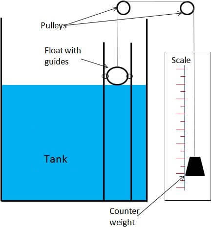
One common form of level measuring system uses a tape or servo motor which is connected to a float. The height can be read as the float moves with liquid level.
Float devices use the buoyancy of a float to indicate the liquid level in the tank. One common approach is to attach the float to a chain. The chain is attached to a counterweight which indicates the level as the float moves up and down. These types of device are often found on large atmospheric storage tanks.

Other devices transfer the buoyancy force to a metering device using a torque tube. The float is connected to the torque tube which twists as the height of the displacement device changes. The twisting force drives the position of a pointer which then indicates liquid level.
For some applications – where the liquid is corrosive, toxic or in some way hazardous – a magnetic level gauge is used.
The float contains a magnet which changes the orientation of small indicator wafers as it moves up and down.
Float Level Indicator Animation :
Note: This animation only for understanding the concept. In Practical the design may change.
Other systems use the float method by sensing the position of the float magnetically or electrically.
Float systems can also be used when measuring granular solids as well as liquids.
Disadvantages
Wire Guided Float Detectors
For large level measurements (ie. 20m), wire-guided float detectors can be used. The guide wires are connected to top and bottom anchors and assist in positioning the float as it moves with the fluid level. The tape is connected to the top of the float and runs directly up and over pulleys then down to the gauging head which is outside the tank at a suitable level for viewing.
The perforated tape is received in the gauge head by a sprocketed counter drive. Any slackness in the tape is taken up by the tape storage reel which is tensioned. Tensioning of the tape storage reel is sufficient to ensure correct measurement, while not affecting the position of the float.
The shaft on the counter drive rotates as the float moves the perforated tape up and down. The rotary motion of the shaft is used to give a metric readout.
In atmospheric conditions, a seal is used to protect the sensing head from the process fluid. However in pressurised applications, it is better to fill the head with the sensing fluid, particularly if the fluid is clean and lubricating.
Application Limitations
Float and tape systems have a common problem with the tape hanging up. This often occurs if the long guide pipes are not perfectly vertical, where the tape rubs against the inside of the pipes.
Another common problem is with corrosion or dirt, where the tape can be held in place while the float is moving. These problems are more likely to result in a lower than actual reading.
The force from the float weight is usually great enough to overcome the friction of the tape against the impurities, whereas the force of the take-up device may not. Tanks controlled using tape level gauges will often overflow when the tape is stuck.
This problem can be protected against by the use of a separate high level switch.
More advanced controllers are available that monitor tank capacity and pumping rates to check the actual level, rate of change and direction of change.
Summary
One of the main limitations is the high maintenance required in order to keep the tape clean and prevent it from gumming up. This is old technology and is seldom used.
Learn the example of flip-flop PLC program for lamps application using the ladder logic to…
In this article, you will learn the STAR DELTA programming using PLC controller to start…
Lube oil consoles of rotary equipment packages in industrial process plants are usually equipped with…
Rotating equipment packages such as pumps, compressors, turbines need the lube oil consoles for their…
This article explains how to blink lights in ladder logic with a detailed explanation video…
In this article, a simple example will teach you the conversion from Boolean algebra to…
View Comments
What is the current cost of the float & weight type of level indicator?
IOS app pls........................