Fire & Gas System

Flame Detector Testing Procedure

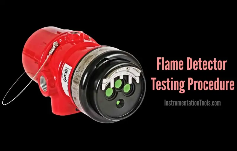
Here in this article, we discussed the general testing or healthiness checking procedure of an Flame Detector which is used in the fire and gas systems.

Flame Detector Testing

Flame Detector Testing Procedure

Before starting the job, take the proper work permit and inform to all the respective departments. Then do force the respective logics or interlocks if any (like fire suppression systems activation etc)

  • Prior to testing of Flame Detector we should check LED Visibility of the Flame Detector. It should be blinking green. This can be seen on the flame Detector.
  • Check the + 24 Volts DC Supply of the Flame Detector between + and – terminal of the Flame Detector.
  • Take UV / IR Testing Torch for testing of Flame Detector.
  • Before applying UV / IR rays to the Flame Detector, clean the detectors display by cotton cloth. It should be always cleaned for detecting the UV / IR rays. Otherwise Fault LED indication appears.
  • Apply the UV /IR rays from UV / IR torch to the Flame detector.
  • Resolution can be adjusted for the torch for checking the detector from short and long distance.
  • After 3 seconds alarm appears and hooter is activated.
  • Flame detectors Red LED indication will be ON (steady Red).
  • Acknowledge the Flame detector’s alarm & silence the hooter.
  • Note down the alarm tag and descriptions from the HMI or workstation. The alarm details must match with the flame detector tag number and installed location.
  • Confirm the flame detector activation status from the respective graphics page. You have to visually identify the color change signals of the respective flame detector on the graphics.
  • Remove the UV / IR test torch.
  • Reset the alarm of the Flame Detector. Now Red LED Indication is off.
  • Now the Flame Detector is working OK and Green LED indication is blinking.
  • Repeat the above procedure for all the remaining flame detectors.
  • Normalize the forced interlocks or logics if any.
  • Close the work permit.

Note: The mentioned voltages, terminals, LED colors may vary as per the vendor or model of the Flame Detector.

Author: V Hemanth

Read Next:

You've successfully subscribed !

View Comments

Share

Recent Articles

  • PLC Tutorials

Conveyor Sorting Machine PLC Program with Calculation Function

The conveyor sorting machine is widely used in the packing industries using the PLC program…

5 days ago
  • PLC Tutorials

Example of Flip-Flop PLC Program for Lamps Application

Learn the example of flip-flop PLC program for lamps application using the ladder logic to…

5 days ago
  • PLC Tutorials

STAR DELTA Programming using PLC Controller

In this article, you will learn the STAR DELTA programming using PLC controller to start…

5 days ago
  • Instrumentation Design

Single and Three Phase Immersion Electrical Heaters Wiring Circuits

Lube oil consoles of rotary equipment packages in industrial process plants are usually equipped with…

2 days ago
  • Instrumentation Design

Immersion Heaters in Lube Oil Consoles

Rotating equipment packages such as pumps, compressors, turbines need the lube oil consoles for their…

5 days ago
  • PLC Tutorials

How to Blink Lights in Ladder Logic?

This article explains how to blink lights in ladder logic with a detailed explanation video…

4 weeks ago