Inst ToolsInst ToolsInst Tools
  • Courses
  • Automation
    • PLC
    • Control System
    • Safety System
    • Communication
    • Fire & Gas System
  • Instrumentation
    • Design
    • Pressure
    • Temperature
    • Flow
    • Level
    • Vibration
    • Analyzer
    • Control Valve
    • Switch
    • Calibration
    • Erection & Commissioning
  • Interview
    • Instrumentation
    • Electrical
    • Electronics
    • Practical
  • Q&A
    • Instrumentation
    • Control System
    • Electrical
    • Electronics
    • Analog Electronics
    • Digital Electronics
    • Power Electronics
    • Microprocessor
  • Request
Search
  • Books
  • Software
  • Projects
  • Process
  • Tools
  • Basics
  • Formula
  • Power Plant
  • Root Cause Analysis
  • Electrical Basics
  • Animation
  • Standards
  • 4-20 mA Course
  • Siemens PLC Course
Reading: Flame Detector Testing Procedure
Share
Font ResizerAa
Inst ToolsInst Tools
Font ResizerAa
  • Courses
  • Design
  • PLC
  • Interview
  • Control System
Search
  • Courses
  • Automation
    • PLC
    • Control System
    • Safety System
    • Communication
    • Fire & Gas System
  • Instrumentation
    • Design
    • Pressure
    • Temperature
    • Flow
    • Level
    • Vibration
    • Analyzer
    • Control Valve
    • Switch
    • Calibration
    • Erection & Commissioning
  • Interview
    • Instrumentation
    • Electrical
    • Electronics
    • Practical
  • Q&A
    • Instrumentation
    • Control System
    • Electrical
    • Electronics
    • Analog Electronics
    • Digital Electronics
    • Power Electronics
    • Microprocessor
  • Request
Follow US
All rights reserved. Reproduction in whole or in part without written permission is prohibited.
Inst Tools > Blog > Fire & Gas System > Flame Detector Testing Procedure

Flame Detector Testing Procedure

The general testing, calibration or healthiness checking procedure of an Flame Detector used in the fire and gas systems.

Last updated: August 27, 2020 9:37 am
Editorial Staff
Fire & Gas System
3 Comments
Share
3 Min Read
SHARE

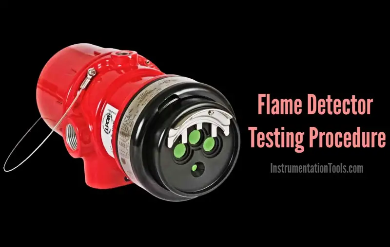
Here in this article, we discussed the general testing or healthiness checking procedure of an Flame Detector which is used in the fire and gas systems.

Flame Detector Testing

Flame Detector Testing Procedure

Before starting the job, take the proper work permit and inform to all the respective departments. Then do force the respective logics or interlocks if any (like fire suppression systems activation etc)

  • Prior to testing of Flame Detector we should check LED Visibility of the Flame Detector. It should be blinking green. This can be seen on the flame Detector.
  • Check the + 24 Volts DC Supply of the Flame Detector between + and – terminal of the Flame Detector.
  • Take UV / IR Testing Torch for testing of Flame Detector.
  • Before applying UV / IR rays to the Flame Detector, clean the detectors display by cotton cloth. It should be always cleaned for detecting the UV / IR rays. Otherwise Fault LED indication appears.
  • Apply the UV /IR rays from UV / IR torch to the Flame detector.
  • Resolution can be adjusted for the torch for checking the detector from short and long distance.
  • After 3 seconds alarm appears and hooter is activated.
  • Flame detectors Red LED indication will be ON (steady Red).
  • Acknowledge the Flame detector’s alarm & silence the hooter.
  • Note down the alarm tag and descriptions from the HMI or workstation. The alarm details must match with the flame detector tag number and installed location.
  • Confirm the flame detector activation status from the respective graphics page. You have to visually identify the color change signals of the respective flame detector on the graphics.
  • Remove the UV / IR test torch.
  • Reset the alarm of the Flame Detector. Now Red LED Indication is off.
  • Now the Flame Detector is working OK and Green LED indication is blinking.
  • Repeat the above procedure for all the remaining flame detectors.
  • Normalize the forced interlocks or logics if any.
  • Close the work permit.

Note: The mentioned voltages, terminals, LED colors may vary as per the vendor or model of the Flame Detector.

Author: V Hemanth

Read Next:

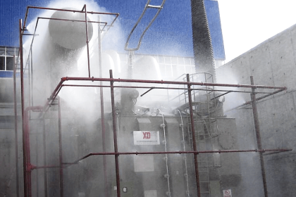
  • Gas Suppression System
  • Rate of Rise Thermal Detectors
  • End of Line (EOL) Resistor
  • Fire System Loop Check
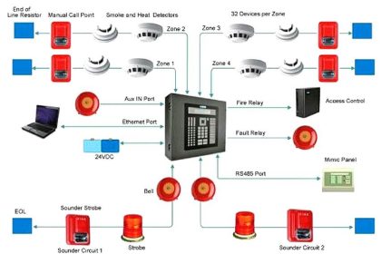
  • Fire Detection System
Don't Miss Our Updates
Be the first to get exclusive content straight to your email.
We promise not to spam you. You can unsubscribe at any time.
Invalid email address
You've successfully subscribed !

Continue Reading

Types of Fire Detectors
Catalytic Type Gas Sensor Principle
Fire Water Spray Systems Principle
Fire Extinguishers Mock Test
Fire Water Sprinklers Working Principle
Smoke Detector Testing Procedure
Share This Article
Facebook Whatsapp Whatsapp LinkedIn Copy Link
Share
3 Comments
  • Muhammad Kaleem says:
    April 3, 2023 at 12:38 pm

    dear
    send me flame detector testing graphs and UV/IR torch price.

    BR
    Muhammad Kaleem

    Reply
  • Sankara Rao Manne says:
    June 26, 2023 at 1:52 pm

    Whether UV/IR torch can be used in Zone1 & Zone2 areas

    Reply
    • Editorial Staff says:
      June 26, 2023 at 2:28 pm

      Yes, Refer this Article – https://engineerscommunity.com/t/uv-ir-torch-in-zone1-zone2-areas/36479

      Reply

Leave a Reply Cancel reply

Your email address will not be published. Required fields are marked *

Stay Connected

128.3kFollowersLike
69.1kFollowersFollow
210kSubscribersSubscribe
38kFollowersFollow

Categories

Explore More

Fixed Gas Detectors vs. Portable Gas Detectors
Interview Questions on Fire Alarm System
Deluge System for Transformer Protection Animation
Calibration of Gas Detectors
How to identify location of Fire Detectors
Why Fire and Gas Detectors are 3-Wire types instead of 2 Wire?
Manual Call Point Testing Procedure
Basics of Fire Detection and Alarm System

Keep Learning

Purpose of End of Line (EOL) Resistor in Fire & Gas System ?

Why we use End of Line (EOL) Resistor in Fire and Gas System ?

Gas Detection System Abbreviations

Gas Detection System Abbreviations

Gas Detection Excel Converters

Industrial Flame Detectors

Industrial Flame Detectors

Deluge Valve Operation

Deluge Valve Working Principle

foam fire protection system

Basics of Foam Fire Fighting System

What are Fire Branches?

What are Fire Branches?

Fire Hydrant System

Basics of Fire Fighting Hydrant Systems

Learn More

Types of Angular Velocity Measurement

Types of Angular Velocity Measurement

Passing Control Valves Cause Yearly Losses

Passing Control Valves Cause Yearly Losses in Production Plant

Selection of Weighing Balance

Selection of Weighing Balance and Weight for Calibration

Auto Cane Feed Control System using DCS

Auto Cane Feed Control System using DCS – Sugar Factory

Ammonia Gas Detector Calibration

Ammonia Gas Detector Working Principle and Calibration

Wireless HART Transmitter

How to Commission WirelessHART Transmitter With Gateway

Real-time and historical SCADA Trends

What are Trends in SCADA?

PLC Cabinet

PLC Programming Videos

Menu

  • About
  • Privacy Policy
  • Copyright

Quick Links

  • Learn PLC
  • Helping Hand
  • Part Time Job

YouTube Subscribe

Follow US
All rights reserved. Reproduction in whole or in part without written permission is prohibited.
Welcome Back!

Sign in to your account

Username or Email Address
Password

Lost your password?