Inst ToolsInst ToolsInst Tools
  • Courses
  • Automation
    • PLC
    • Control System
    • Safety System
    • Communication
    • Fire & Gas System
  • Instrumentation
    • Design
    • Pressure
    • Temperature
    • Flow
    • Level
    • Vibration
    • Analyzer
    • Control Valve
    • Switch
    • Calibration
    • Erection & Commissioning
  • Interview
    • Instrumentation
    • Electrical
    • Electronics
    • Practical
  • Q&A
    • Instrumentation
    • Control System
    • Electrical
    • Electronics
    • Analog Electronics
    • Digital Electronics
    • Power Electronics
    • Microprocessor
  • Request
Search
  • Books
  • Software
  • Projects
  • Process
  • Tools
  • Basics
  • Formula
  • Power Plant
  • Root Cause Analysis
  • Electrical Basics
  • Animation
  • Standards
  • 4-20 mA Course
  • Siemens PLC Course
Reading: FF Function Blocks
Share
Font ResizerAa
Inst ToolsInst Tools
Font ResizerAa
  • Courses
  • Design
  • PLC
  • Interview
  • Control System
Search
  • Courses
  • Automation
    • PLC
    • Control System
    • Safety System
    • Communication
    • Fire & Gas System
  • Instrumentation
    • Design
    • Pressure
    • Temperature
    • Flow
    • Level
    • Vibration
    • Analyzer
    • Control Valve
    • Switch
    • Calibration
    • Erection & Commissioning
  • Interview
    • Instrumentation
    • Electrical
    • Electronics
    • Practical
  • Q&A
    • Instrumentation
    • Control System
    • Electrical
    • Electronics
    • Analog Electronics
    • Digital Electronics
    • Power Electronics
    • Microprocessor
  • Request
Follow US
All rights reserved. Reproduction in whole or in part without written permission is prohibited.
Inst Tools > Blog > Communication > FF Function Blocks

FF Function Blocks

Last updated: March 28, 2018 5:23 am
Editorial Staff
Communication
No Comments
Share
3 Min Read
SHARE

Data-processing modules within FF systems are known as function blocks. Sometimes these blocks serve merely to catalogue data, while in other instances the blocks execute specific algorithms useful for process measurement and control. These “blocks” are not physical entities, but rather abstract software objects – they exist only as bits of data and instructions in computer memory. However, the blocks are represented on FF computer configuration displays as rectangular objects with input ports on the left-hand side and output ports on the right-hand side. The construction of a working control system comprised of FF devices consists of linking the outputs of certain function blocks with the inputs of other function blocks via configuration software and computer-based tools. This usually takes the form of using a computer to draw connecting lines between the output and input ports of different function blocks.

Analog function blocks versus digital function blocks

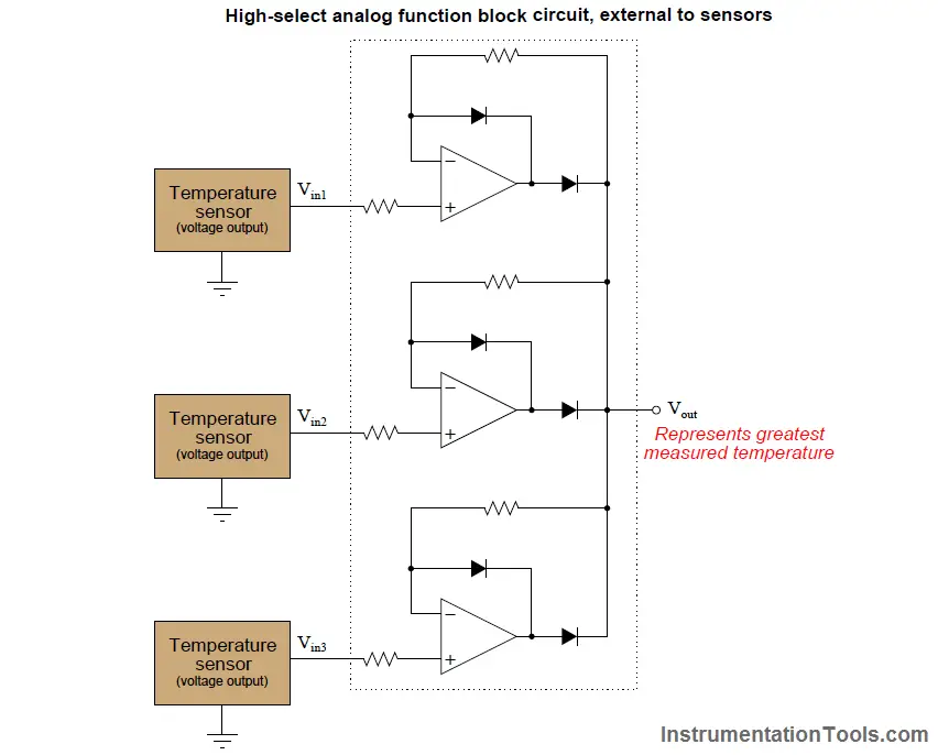
Function-block programming in general strongly resembles the design philosophy of legacy analog based computer systems, where specific functions (addition, subtraction, multiplication, ratio, time integration, limiting, and others) were encapsulated in discrete operational amplifier circuits, and whole systems were built by connecting function blocks together in whatever patterns were desired to achieve a design goal. Here with Fieldbus programming, the function blocks are virtual (bits and data structures in digital memory) rather than real analog circuits, and the connections between blocks are merely pointer assignments in digital memory rather than actual “patch cable” connections between circuit boards.

An example contrasting analog circuit design with Fieldbus function-block design appears here, both systems selecting the greatest temperature signal to be the output. The system on the first figure side receives analog voltage signals from three temperature sensors, using a network of operational amplifiers, diodes, and resistors to select the greatest voltage signal to be the output. The system on the second figure side uses three Fieldbus transmitters to sense temperature, the greatest temperature signal selected by an algorithm (the ISEL function block) running in a Fieldbus device. The device running the ISEL function could be one of the three FF temperature transmitters, or another device on the segment:

High-select analog function block

Input function blocks

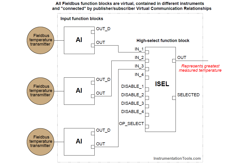
Instead of analog voltage signals sent by wire to special-function circuit modules, FOUNDATION Fieldbus uses digital messages sent over an H1 network segment to special-function software “blocks” running inside ordinary Fieldbus devices. The lines connecting different function blocks together in a FOUNDATION Fieldbus system show the sources and destinations of these digital messages. If two FF function blocks reside in different FF devices, the connecting lines represent publisher/subscriber communication assignments coordinated by the Link Active Scheduler (LAS) device.

Don't Miss Our Updates
Be the first to get exclusive content straight to your email.
We promise not to spam you. You can unsubscribe at any time.
Invalid email address
You've successfully subscribed !

Continue Reading

HART Communication Tutorial Part 2
Difference Between Serial and Parallel Communication
What is a Patch Panel? Types and Uses in Networking
HART Communication Tutorial Part 1
H1 FF Device Configuration and Commissioning
Different Fieldbus Network Topologies
Share This Article
Facebook Whatsapp Whatsapp LinkedIn Copy Link
Share
Leave a Comment

Leave a Reply Cancel reply

Your email address will not be published. Required fields are marked *

Stay Connected

128.3kFollowersLike
69.1kFollowersFollow
210kSubscribersSubscribe
38kFollowersFollow

Categories

Explore More

Latest ProfiBus Questions and Answers
Basics for CAN Bus Protocol – Controller Area Network
Fiber Optic Cable Construction
Fiber Optic Sensors
Foundation Fieldbus Tutorials
Difference Between Modbus TCP IP and Profinet
Types of Wireless Technologies in Industrial Automation
Foundation Fieldbus Signal Conversion Formula

Keep Learning

Profibus Listener Principle

Profibus Listener

HART Communication Tutorial 1

HART Communication Tutorial Part 4

Fiber Optic Patch Cord

What is a Fiber Optic Patch Cord? – Types, Explained

Multi-mode optical fiber

Multi-mode and Single-mode Optical Fibers

HART Multidrop Network

What is HART Protocol ?

Introduction to Fieldbus Function Blocks

RAID stands for Redundant Array of Independent Disks

What is Raid Parity? – Types, Advantages, Disadvantages

Types of Cable Lengths in Ethernet Network

Types of Cable Lengths in Ethernet Network

Learn More

Guided wave radar Measurement Principle

Guided Wave Radar – Principle, Limitations, Installation

Industrial Instrumentation Questions & Answers

Industrial Instrumentation Questions & Answers

Opposite Acting Control Valves Application

PLC Ladder Logic for Opposite Acting Control Valves Application

Feedback Pneumatic Load cell Objective Questions

Feedback Pneumatic Load cell Objective Questions

Analyzers Questions and Answers

Biosensors Questions & Answers

Impulse Steam Trap

Impulse Steam Trap

PLC Instructions

Program Flow Control Instructions in PLC Programming

Why is IEC 60269 Important

Why is IEC 60269 Important? – Electrical Applications

Menu

  • About
  • Privacy Policy
  • Copyright

Quick Links

  • Learn PLC
  • Helping Hand
  • Part Time Job

YouTube Subscribe

Follow US
All rights reserved. Reproduction in whole or in part without written permission is prohibited.
Welcome Back!

Sign in to your account

Username or Email Address
Password

Lost your password?