Determine the final effect of each fault for this pneumatic force-balance system:
Pneumatic Force-balance System
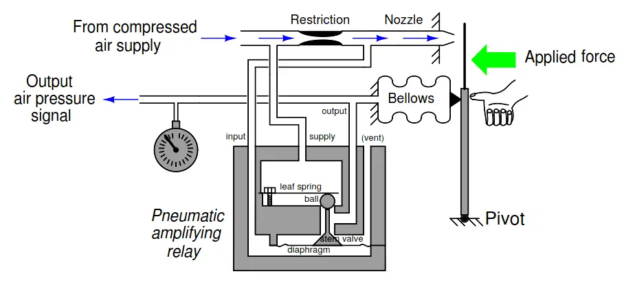
- Clogged nozzle
- Clogged restriction
- Clogged tube at supply port of amplifying relay
- Broken leaf spring inside amplifying relay
- Major hole or tear in the diaphragm inside the amplifying relay
Be sure to explain the final effects of each of these faults!
Answer:
- Clogged nozzle: output pressure saturates high
- Clogged restriction: output pressure saturates low
- Clogged tube at supply port of amplifying relay: output pressure saturates low
- Broken leaf spring inside amplifying relay: output pressure may saturate high or possibly oscillate
- Major hole or tear in diaphragm inside amplifying relay: The system responds very little to the applied force.
Interest to add any further points? Share your answers with us through the below comments section.
Read Next:
- Motion-Balance Instrument
- PLC Pneumatic Circuit
- Types of Allen Bradley PLC
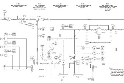
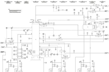
- Pneumatic P&ID Diagrams
- Pneumatic Instrumentation
Credits: Tony R. Kuphaldt