Inst ToolsInst ToolsInst Tools
  • Courses
  • Automation
    • PLC
    • Control System
    • Safety System
    • Communication
    • Fire & Gas System
  • Instrumentation
    • Design
    • Pressure
    • Temperature
    • Flow
    • Level
    • Vibration
    • Analyzer
    • Control Valve
    • Switch
    • Calibration
    • Erection & Commissioning
  • Interview
    • Instrumentation
    • Electrical
    • Electronics
    • Practical
  • Q&A
    • Instrumentation
    • Control System
    • Electrical
    • Electronics
    • Analog Electronics
    • Digital Electronics
    • Power Electronics
    • Microprocessor
  • Request
Search
  • Books
  • Software
  • Projects
  • Process
  • Tools
  • Basics
  • Formula
  • Power Plant
  • Root Cause Analysis
  • Electrical Basics
  • Animation
  • Standards
  • 4-20 mA Course
  • Siemens PLC Course
Reading: Experimentation of Transfer Function
Share
Font ResizerAa
Inst ToolsInst Tools
Font ResizerAa
  • Courses
  • Design
  • PLC
  • Interview
  • Control System
Search
  • Courses
  • Automation
    • PLC
    • Control System
    • Safety System
    • Communication
    • Fire & Gas System
  • Instrumentation
    • Design
    • Pressure
    • Temperature
    • Flow
    • Level
    • Vibration
    • Analyzer
    • Control Valve
    • Switch
    • Calibration
    • Erection & Commissioning
  • Interview
    • Instrumentation
    • Electrical
    • Electronics
    • Practical
  • Q&A
    • Instrumentation
    • Control System
    • Electrical
    • Electronics
    • Analog Electronics
    • Digital Electronics
    • Power Electronics
    • Microprocessor
  • Request
Follow US
All rights reserved. Reproduction in whole or in part without written permission is prohibited.
Inst Tools > Blog > Multiple Choice Questions > Experimentation of Transfer Function

Experimentation of Transfer Function

Last updated: November 27, 2021 5:40 pm
Editorial Staff
Multiple Choice Questions
No Comments
Share
5 Min Read
SHARE

Experimentation of Transfer Function MCQ

1. The impulse response of a LTI system is a unit step function, then the corresponding transfer function is

a) 1/s
b) 1/s2
c) 1
d) s

Answer: a

Explanation: The impulse response of a LTI system is the transfer function itself and hence for the unit step function . As input then the transfer function will be 1/s.

2. For a type one system, the steady – state error due to step input is equal to

a) Infinite
b) Zero
c) 0.25
d) 0.5

Answer: b

Explanation: The steady state error is defined as the error between the final value and the desired response and the difference in the value of both will be the steady state error due to step input for type one system is zero.

3. The equation 2s4+s3+3s2+5s+10=0 has roots in the left half of s–plane:

a) One
b) Two
c) Three
d) Four

Answer: b

Explanation: The roots of the equation can be calculated using Routh-Hurwitz criterion and hence there are 2 sign changes in the first column of the row and therefore the two roots lie on the right half of s-plane.

4. If the Nyquist plot of the loop transfer function G (s)H (s) of a closed-loop system encloses the (1, j0) point in the G (s)H (s) plane, the gain margin of the system is

a) Zero
b) Greater than zero
c) Less than zero
d) Infinity

Answer: c

Explanation: Nyquist plot deals with the open loop poles and zero and equals the encirclements to the open loop poles of the system.

5. Consider the function F (s) =5/s (s2+s+2) , where F (s) is the Laplace transform f (t). Then the final value theorem is equal to

a) 5
b) 5/2
c) Zero
d) Infinity

Answer: b

Explanation: Final value theorem is given for the stable system only and this is a type 1 system and for step input the final value can be calculated as 5/2.

6. The transfer function of a phase-lead controller is given by

a) (1+aTs)/(1+Ts) , a>1 T>0
b) (1+aTs)/(1+Ts) , a<1 T>0
c) (1-aTs)/(1+Ts) , a>1 T>0
d) (1±Ts)/(1+Ts) , a<1 T>0

Answer: a

Explanation: For the phase lead controller in which the stability and speed of response is more for the system, the magnitude of the pole must be greater than the magnitude of the zero.

7. If the system matrix of a linear time invariant continuous system is given by Its characteristic equation is given by:

a) s2+5s+3=0
b) s2-3s-5=0
c) s2+3s+5=0
d) s2+s+2=0

Answer: a

Explanation: The transfer function is calculated by the state variable analysis and hence the transfer function is calculated by state transition matrix and taking the inverse Laplace transform.

8. Given a unity feedback control system with G (s) = K/s(s+4), the value of K for which the damping ratio is 0.5.

a) 1
b) 16
c) 64
d) 32

Answer: b

Explanation: The value is found by using the Routh- Hurwitz criteria and equating one of the row of the Routh-Hurwitz criteria equal to zero and hence finding the value of K.

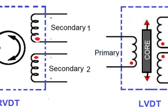
9. The LVDT is used in the measurement of:

a) Displacement
b) Acceleration
c) Velocity
d) Humidity

Answer: a

Explanation: The LVDT is the linear variable differential transformer and it is used to calculate the displacement with the inductor process.

10. A system with gain margin close to unity and phase margin close to zero is :

a) Highly stable
b) Oscillatory
c) Relatively stable
d) Unstable

Answer: c

Explanation: A system is relative stable not stable if the phase margin is close to zero then the stability is checked by gain margin.

Don't Miss Our Updates
Be the first to get exclusive content straight to your email.
We promise not to spam you. You can unsubscribe at any time.
Invalid email address
You've successfully subscribed !

Continue Reading

Block diagram Algebra Objective Questions
Fundamentals of Radiochemical Methods Questions
Optimal Control Problems – Part 2
Silica Analyzer Questions & Answers
Time Response of Second Order Systems – II
X-Ray Fluorescence Spectrometry Questions and Answers
Share This Article
Facebook Whatsapp Whatsapp LinkedIn Copy Link
Share
Leave a Comment

Leave a Reply Cancel reply

Your email address will not be published. Required fields are marked *

Stay Connected

128.3kFollowersLike
69.1kFollowersFollow
210kSubscribersSubscribe
38kFollowersFollow

Categories

Explore More

Hydrogen and Glass Electrodes Questions & Answers
Gas Chromatograph- Mass Spectrometer
Electron Spin Resonance
Infrared Spectrometers Questions & Answers
Process Control Questions & Answers
PLC Interview Questions and Answers
Top 1000 Instrumentation Engineering Objective Questions
Quadrupole Mass Spectrometer

Keep Learning

Stability in Frequency Domain

Preliminary Considerations of Classical Design

Analyzers Questions and Answers

Amino-Acid Analyzers Questions & Answers

Control Loops Multiple Choice Questions

Control Loop Multiple Choice Questions

Spectrometers Questions and Answers

Fluorescent Spectrometer Questions & Answers

Mass Spectrometer Questions and Answers

Tandem Mass Spectroscopy

State Variable Analysis and Design

Pole Placement by State Feedback

Time Response Analysis

State Variable Analysis – Part II

Root Locus Concepts Objective Questions

Root Locus in Control Systems

Learn More

Field Instruments Questions and Answers

Basics of Amplifiers Interview Questions

Ultrasonic level measurement

Ultrasonic Level Measurement

Power Supply Circuit Working Animation

Power Supply Circuit Working Animation

Conveyor Control with Main Motor and Backup Motor

Conveyor Operation with a Backup Motor using PLC Ladder Diagram

PLC Modbus Communication

Introduction to Modbus – Reading and Writing Data

multi-hole-restriction-orifice-plate

Basics of Restriction Orifice (RO) – Types, Applications, Standards

Transit Time flow meter Theory

Transit Time Flow Meter Principle

Concept of Interlocking in PLC

Concept of Interlocking in PLC

Menu

  • About
  • Privacy Policy
  • Copyright

Quick Links

  • Learn PLC
  • Helping Hand
  • Part Time Job

YouTube Subscribe

Follow US
All rights reserved. Reproduction in whole or in part without written permission is prohibited.
Welcome Back!

Sign in to your account

Username or Email Address
Password

Lost your password?