Inst ToolsInst ToolsInst Tools
  • Courses
  • Automation
    • PLC
    • Control System
    • Safety System
    • Communication
    • Fire & Gas System
  • Instrumentation
    • Design
    • Pressure
    • Temperature
    • Flow
    • Level
    • Vibration
    • Analyzer
    • Control Valve
    • Switch
    • Calibration
    • Erection & Commissioning
  • Interview
    • Instrumentation
    • Electrical
    • Electronics
    • Practical
  • Q&A
    • Instrumentation
    • Control System
    • Electrical
    • Electronics
    • Analog Electronics
    • Digital Electronics
    • Power Electronics
    • Microprocessor
  • Request
Search
  • Books
  • Software
  • Projects
  • Process
  • Tools
  • Basics
  • Formula
  • Power Plant
  • Root Cause Analysis
  • Electrical Basics
  • Animation
  • Standards
  • 4-20 mA Course
  • Siemens PLC Course
Reading: Exclusive Control Valve Sequence
Share
Notification Show More
Font ResizerAa
Inst ToolsInst Tools
Font ResizerAa
  • Courses
  • Design
  • PLC
  • Interview
  • Control System
Search
  • Courses
  • Automation
    • PLC
    • Control System
    • Safety System
    • Communication
    • Fire & Gas System
  • Instrumentation
    • Design
    • Pressure
    • Temperature
    • Flow
    • Level
    • Vibration
    • Analyzer
    • Control Valve
    • Switch
    • Calibration
    • Erection & Commissioning
  • Interview
    • Instrumentation
    • Electrical
    • Electronics
    • Practical
  • Q&A
    • Instrumentation
    • Control System
    • Electrical
    • Electronics
    • Analog Electronics
    • Digital Electronics
    • Power Electronics
    • Microprocessor
  • Request
Follow US
All rights reserved. Reproduction in whole or in part without written permission is prohibited.
Inst Tools > Blog > Control Valves > Exclusive Control Valve Sequence

Exclusive Control Valve Sequence

Last updated: March 21, 2019 4:18 pm
Editorial Staff
Control Valves
No Comments
Share
3 Min Read
SHARE

Other applications for split-ranged control valves call for a form of valve sequencing where both valves are fully closed at a 50% controller output signal, with one valve opening fully as the controller output drives toward 100% and the other valve opening fully as the controller output goes to 0%.

The nature of this valve sequencing is to have an “either-or” throttled path for process fluid. That is, either process fluid flows through one valve or through the other, but never through both at the same time.

Exclusive Control Valve Sequence

A practical example of this form of split-ranging is reagent feed for a pH neutralization process, where the pH value of process liquid is brought closer to neutral by the addition of either acid or caustic reagent liquids:

Exclusive Control Valve Sequence

Here, a pH analyzer monitors the pH value of the liquid solution and a single pH controller commands two reagent valves to open when needed. If the process pH begins to increase, the controller output signal increases as well (direct action) to open up the acid valve.

The addition of acid to the mixture will have the effect of lowering the mixture’s pH value. Conversely, if the process pH begins to decrease, the controller output signal will decrease as well, closing the acid valve and then opening the caustic valve. The addition of caustic to the mixture will have the effect of raising the mixture’s pH value.

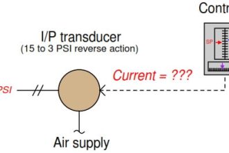
Both reagent control valves operate from the same 3 to 15 PSI pneumatic signal output by the I/P transducer (AY), but the two valves’ calibrated ranges are not the same.

The Air-To-Open acid valve has an operating range of 9 to 15 PSI, while the Air-To-Close caustic valve has an operating range of 9 to 3 PSI.

The following table shows the relationship between valve opening for each control valve and the controller’s output:

relationship between valve opening for each control valve and the controller’s output

Again, we may express the two valves’ exclusive relationship in the form of a graph, with colored stripes representing valve opening:

two valves’ exclusive relationship

Exclusive-sequenced control valves are used in applications where it would be undesirable to have both valves open simultaneously.

In the example given of a pH neutralization process, the goal here is for the controller to add either acid reagent or caustic reagent to “push” the pH value either direction as needed.

However, simultaneously adding both acid and caustic to the process would be wasteful, as one reagent would simply neutralize the other with no benefit to the process liquid itself.

Also Read : Types of Valve Actuators

Don't Miss Our Updates
Be the first to get exclusive content straight to your email.
We promise not to spam you. You can unsubscribe at any time.
Invalid email address
You've successfully subscribed !

Continue Reading

Snap Acting Relay Working Principle
What is a Pneumatic Actuator ?
What is Poppet Valve? When we Use a Poppet Valve?
What is Tilting Disk Check Valve ?
How Globe Valves Work ?
What is a Disc Valve ?
Share This Article
Facebook Whatsapp Whatsapp LinkedIn Copy Link
Share
Leave a Comment

Leave a Reply Cancel reply

Your email address will not be published. Required fields are marked *

Stay Connected

128.3kFollowersLike
69.1kFollowersFollow
210kSubscribersSubscribe
38kFollowersFollow

Categories

Explore More

Dampers and Louvres
How is Pressure Drop Calculated through a Valve ?
SIS Emergency Block Valves (EBV)
Valve Seat Leakage Test
Self Actuated Pressure Control Valve Principle
What is a Fail-Close Valve? – Advantages and Disadvantages
Control Valve in Nutshell – Valve Design and Selection Factors
Solenoid Valves Practical Problems

Keep Learning

valve plug and seat damage

Control Valve Erosion Problems

Root Cause Analysis on Hunting of Control Valves

Hunting of Control Valves

Double-acting cylinder - 2

Fluid Power Systems

Butterfly Valve

Butterfly Valves Construction, Types, Stem & Bonnet Assembly

Air Lock Relay Working Principle

Control Valve Air Lock Relay Working Principle

Plug Valve Parts

What is Plug Valve ?

3-way-2-position-solenoid-valve-spring-return

Pneumatic Directional Control Valves

Solenoid Valves Selection Guidelines

Solenoid Valves Selection Guidelines

Learn More

Field Instruments

#11 PLC Best Practices – Instrument for Plausibility Checks

Isometric Projection

Piping and Instrumentation Drawing (P&ID) Tutorials – Part 2

Pictorial Fluid Power Diagram

Hydraulic and Pneumatic P&ID Diagrams and Schematics

Power Electronics Objective Questions

Power Electronics Objective Questions

Flammable Gases and Vapors Class 1 & Class 2

Gas Detectors Standards

Arc Protective Clothing

What is Arc Protective Clothing? – Importance, Features, Materials

Three Valve Manifold

3 Valve Manifold Operation

DC Generator

DC Generator

Menu

  • About
  • Privacy Policy
  • Copyright

Quick Links

  • Learn PLC
  • Helping Hand
  • Part Time Job

YouTube Subscribe

Follow US
All rights reserved. Reproduction in whole or in part without written permission is prohibited.
Welcome Back!

Sign in to your account

Username or Email Address
Password

Lost your password?