Inst ToolsInst ToolsInst Tools
  • Courses
  • Automation
    • PLC
    • Control System
    • Safety System
    • Communication
    • Fire & Gas System
  • Instrumentation
    • Design
    • Pressure
    • Temperature
    • Flow
    • Level
    • Vibration
    • Analyzer
    • Control Valve
    • Switch
    • Calibration
    • Erection & Commissioning
  • Interview
    • Instrumentation
    • Electrical
    • Electronics
    • Practical
  • Q&A
    • Instrumentation
    • Control System
    • Electrical
    • Electronics
    • Analog Electronics
    • Digital Electronics
    • Power Electronics
    • Microprocessor
  • Request
Search
  • Books
  • Software
  • Projects
  • Process
  • Tools
  • Basics
  • Formula
  • Power Plant
  • Root Cause Analysis
  • Electrical Basics
  • Animation
  • Standards
  • 4-20 mA Course
  • Siemens PLC Course
Reading: Elastic Diaphragm Gauge Principle
Share
Font ResizerAa
Inst ToolsInst Tools
Font ResizerAa
  • Courses
  • Design
  • PLC
  • Interview
  • Control System
Search
  • Courses
  • Automation
    • PLC
    • Control System
    • Safety System
    • Communication
    • Fire & Gas System
  • Instrumentation
    • Design
    • Pressure
    • Temperature
    • Flow
    • Level
    • Vibration
    • Analyzer
    • Control Valve
    • Switch
    • Calibration
    • Erection & Commissioning
  • Interview
    • Instrumentation
    • Electrical
    • Electronics
    • Practical
  • Q&A
    • Instrumentation
    • Control System
    • Electrical
    • Electronics
    • Analog Electronics
    • Digital Electronics
    • Power Electronics
    • Microprocessor
  • Request
Follow US
All rights reserved. Reproduction in whole or in part without written permission is prohibited.
Inst Tools > Blog > Pressure Measurement > Elastic Diaphragm Gauge Principle

Elastic Diaphragm Gauge Principle

Last updated: April 11, 2019 12:03 pm
Editorial Staff
Pressure Measurement
No Comments
Share
4 Min Read
SHARE

Principle of Elastic diaphragm gauges

when an elastic transducer (diaphragm is this case) is subjected to a pressure, it deflects. This deflection is proportional to the applied pressure when calibrated.

Description of Elastic diaphragm gauges

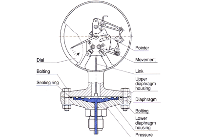
The main parts of the diaphragm which is a thin circular plate (made of springy metal) is fixed firmly around its edges. The diaphragm may either be flat or corrugated.

A corrugated diaphragm has been shown in the diagram where the displacement of the diaphragm is magnified by mechanical means. A flat diaphragm has been shown in the diagram where the displacement of the diaphragm is sensed by a secondary transducer such as a parallel plate capacitor.
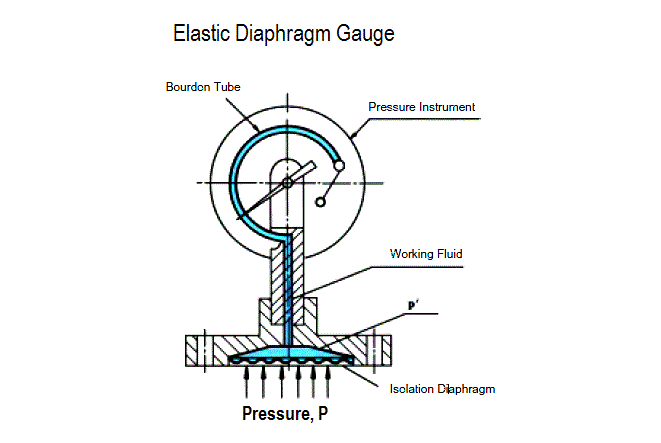
 Principle of Elastic diaphragm gaugesThe top portion of the diaphragm is fixed with a boss of negligible weight. This boss is in-turn connected to a link – sector – pinion arrangement in case of a diaphragm gauge using mechanical means for displacement magnification. A pointer is connected to the pinion which makes it sweep over a pressure calibrated scale. If the displacement is sensed by a secondary transducer such as a parallel plate capacitor, its movable plate is connected to the boss.

Operation of Elastic diaphragm gauges

The bottom side of the diaphragm is exposed to the pressure which is to be measured. Due to the applied pressure, the diaphragm deforms. That is the diaphragm tends to move upwards. This deformation of the diaphragm is proportional to the applied pressure. In a mechanical system, this deformation is magnified by the link – sector – pinion arrangement. That is, the linear displacement of the diaphragm is converted to a magnified rotary motion of the pinion. When the pinion rotates, it makes the pointer attached to it to assume a new position on the pressure calibrated scale which becomes a measure of the applied pressure.

Also See : Diaphragm Gauges Animation

In case of the arrangement with the parallel plate capacitor, the movable plate moves upwards, thus reducing the gap between the plates. This makes the capacitance of the capacitor becomes a measure of the applied pressure. As the top side of the diaphragm is usually subjected to the atmospheric pressure, (generally less than the applied pressure) elastic diaphragm gauges usually read gauge pressure.

Applications of Elastic diaphragm gauges

  • They are used to measure medium pressure.
  • But they can also be used to measure low pressures including vacuum.
  • They are used to measure draft in chimneys of boilers.

Advantages of Elastic diaphragm gauges

  • Best advantage is they cost less
  • They have a linear scale for a wide range
  • They can withstand over pressure and hence they are safe to be used.
  • No permanent zero shift.
  • They can measure both absolute and gauge pressure, that is, differential pressure.

Limitations of Elastic diaphragm gauges

  • Shocks and vibrations affects their performance and hence they are to be protected.
  • When used for high pressure measurement, the diaphragm gets damaged.
  • These gauges are difficult to be repaired.

Note: diaphragm materials

  • Metals : stainless steel, inconel, monel, nickel and beryllium copper.
  • Non – Metals : Nylon, teflon and buna N rubber.
Don't Miss Our Updates
Be the first to get exclusive content straight to your email.
We promise not to spam you. You can unsubscribe at any time.
Invalid email address
You've successfully subscribed !

Continue Reading

Types of Bourdon Tube
Pressure Transmitter Manifolds
Difference between Absolute, Gauge and Differential Pressure Transmitters
All About Instrumentation Impulse Lines
Piston Type Differential Pressure Gauge Principle
How to Measure Pressure in Inches of Water Column
Share This Article
Facebook Whatsapp Whatsapp LinkedIn Copy Link
Share
Leave a Comment

Leave a Reply Cancel reply

Your email address will not be published. Required fields are marked *

Stay Connected

128.3kFollowersLike
69.1kFollowersFollow
210kSubscribersSubscribe
38kFollowersFollow

Categories

Explore More

Differential Pressure Transmitter Calibration Procedure
Pressure Transmitter Applications
Pressure Gauge Problems
Advantages of Pneumatic Systems in the Automotive Industry
Metal Foil Strain Gauge Principle
How to Prepare Pressure Gauge Datasheet ?
Pressure Measurement using Manometer
DP Transmitter Block and Bleed Valves

Keep Learning

U Tube Manometer Principle

U-tube Manometer Principle

U-tube Manometer unEqual Limb Type

U-tube Manometer with equal & unequal limb types

Functions of Pressure Detectors

Functions of Pressure Detectors

Instrument Protection Methods: Seals

Pressure Gauge Water traps and pigtail siphons

Pressure Gauge Water Traps and Pigtail Siphons

Bellow Principle

Bellows

Hammer Effect in Gauges

What is Hammer Effect in Gauges ?

Impulse Line Pressure Testing Procedure

Impulse Line Pressure Testing Procedure

Learn More

Instrumentation Engineering Materials Test

Instrumentation Engineering Materials Test

Fine wire strain gauge

Fine Wire Strain Gauge Principle

purge air blower

SIS – Safety Instrumented System Example

Three phase induction motor nameplate

How to Size a Cable for Industrial AC Motors?

Power Electronics Objective Questions

Voltage Control in Inverters Objective Questions

Ion Spectrometers Questions & Answers

Ion Transducers Questions & Answers

Gas Detector Types

Sensor Technologies in Gas Detectors

Magnetic Flow Meters

Magnetic Flow Meters Installation Guidelines

Menu

  • About
  • Privacy Policy
  • Copyright

Quick Links

  • Learn PLC
  • Helping Hand
  • Part Time Job

YouTube Subscribe

Follow US
All rights reserved. Reproduction in whole or in part without written permission is prohibited.
Welcome Back!

Sign in to your account

Username or Email Address
Password

Lost your password?