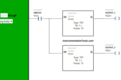
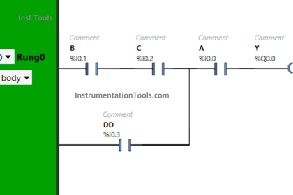
In the ladder logic diagram we can see there is an input contact (N-O) “I0.0” which is a toggle switch in the physical connections to the plc. There is also an output coil addressed as “Q0.0” which can be a Motor, Bulb or any signaling device in the physical connection.
Ladder Logic
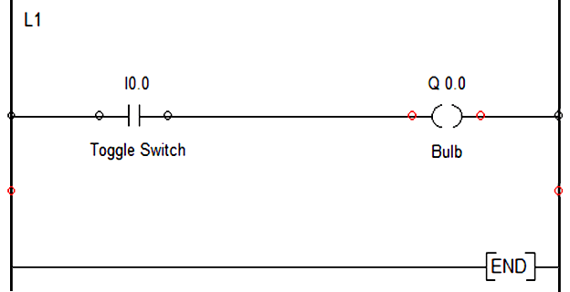
Now, as soon as toggle switch is pressed the NO contact of I0.0 becomes NC and the corresponding rung logic goes true. As a result output coil Q0.0 gets energized and the bulb will ON.
On the other hand, if we want to switch OFF the bulb, the toggle switch is again pressed and I0.0 again becomes an NO contact and rung goes false ,which in turn switches OFF the bulb.
If you liked this article, then please subscribe to our YouTube Channel for PLC and SCADA video tutorials.
You can also follow us on Facebook and Twitter to receive daily updates.
Read Next:
