Draw a ladder logic control circuit for the electric motor of an air compressor, controlled by two pressure switches: one switch turns the motor on when the pressure falls to 80 PSI, while the other switch turns the motor off when the pressure rises to 105 PSI:
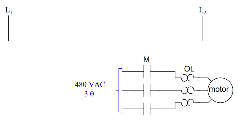
Be sure to include the overload (OL) contact in the 120 volt control circuit (L1 & L2), and include a manual on/off switch as well.
Share Your Answer / Comments
Credits : by Tony R. Kuphaldt – under CC BY 1.0
The conveyor sorting machine is widely used in the packing industries using the PLC program…
Learn the example of flip-flop PLC program for lamps application using the ladder logic to…
In this article, you will learn the STAR DELTA programming using PLC controller to start…
Lube oil consoles of rotary equipment packages in industrial process plants are usually equipped with…
Rotating equipment packages such as pumps, compressors, turbines need the lube oil consoles for their…
This article explains how to blink lights in ladder logic with a detailed explanation video…


View Comments
auxiliary contact of "M" to be paralleled with ON/OFF switch & contact of "80 PSI" to be "NO contact" .