Inst ToolsInst ToolsInst Tools
  • Courses
  • Automation
    • PLC
    • Control System
    • Safety System
    • Communication
    • Fire & Gas System
  • Instrumentation
    • Design
    • Pressure
    • Temperature
    • Flow
    • Level
    • Vibration
    • Analyzer
    • Control Valve
    • Switch
    • Calibration
    • Erection & Commissioning
  • Interview
    • Instrumentation
    • Electrical
    • Electronics
    • Practical
  • Q&A
    • Instrumentation
    • Control System
    • Electrical
    • Electronics
    • Analog Electronics
    • Digital Electronics
    • Power Electronics
    • Microprocessor
Search
  • Books
  • Software
  • Projects
  • Process
  • Tools
  • Basics
  • Formula
  • Power Plant
  • Root Cause Analysis
  • Electrical Basics
  • Animation
  • Standards
  • 4-20 mA Course
  • Siemens PLC Course
Reading: DP Flow Transmitter Re-Ranging Calculation
Share
Notification Show More
Font ResizerAa
Inst ToolsInst Tools
Font ResizerAa
  • Courses
  • Design
  • PLC
  • Interview
  • Control System
Search
  • Courses
  • Automation
    • PLC
    • Control System
    • Safety System
    • Communication
    • Fire & Gas System
  • Instrumentation
    • Design
    • Pressure
    • Temperature
    • Flow
    • Level
    • Vibration
    • Analyzer
    • Control Valve
    • Switch
    • Calibration
    • Erection & Commissioning
  • Interview
    • Instrumentation
    • Electrical
    • Electronics
    • Practical
  • Q&A
    • Instrumentation
    • Control System
    • Electrical
    • Electronics
    • Analog Electronics
    • Digital Electronics
    • Power Electronics
    • Microprocessor
Follow US
All rights reserved. Reproduction in whole or in part without written permission is prohibited.
Inst Tools > Blog > Flow Measurement > DP Flow Transmitter Re-Ranging Calculation

DP Flow Transmitter Re-Ranging Calculation

DP Flow Transmitter Re-Ranging Calculation is used to find the DP Flow transmitter revised flow with Existing DP, Existing Flow & New DP.

Last updated: October 31, 2023 10:51 am
Editorial Staff
Flow Measurement Instrumentation Tools
16 Comments
Share
2 Min Read
SHARE

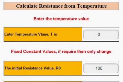
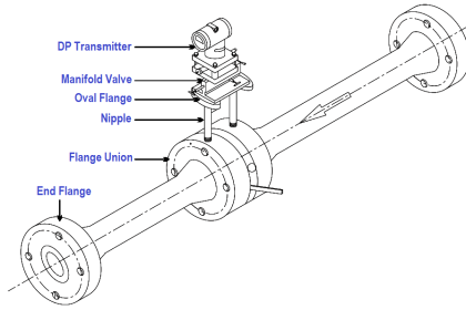
DP Flow Transmitter Re-Range: This tool is used to calculate the DP Flow transmitter revised flow with the following inputs: Existing DP, Existing Flow, and revised DP.

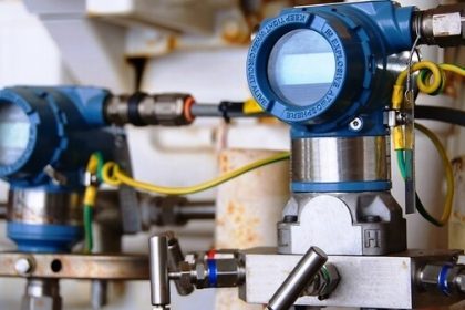
This tool is primarily used for orifice-based flow meters. Also useful for flow transmitters that work on Differential Pressure applications.

Generally, we calibrate our transmitter as per the datasheet of the orifice. But sometimes the measured DP of the transmitter will be out of range or more than the maximum scale of DP, so we have to re-range the DP flow transmitter.

For these applications, we use the below-mentioned formula to calculate the maximum flow of the transmitter.

DP Flow Transmitter Re-Ranging

This calculation tool is used to calculate the revised flow range of a DP Flow transmitter.

The formula for calculating the DP Flow Transmitter Re-Range value.

DP Flow Transmitter Re-Ranging calculation Formula

Where,

Existing DP    = DP value as per orifice datasheet
Existing Flow  =  Flow value as per orifice datasheet
Revised DP    =  Actual DP value in the field
Revised Flow  =  Calculated transmitter flow max range.

Note:

1. The Existing DP and revised DP must be in the same units like bar, mbar, mmh20, etc.
2. The Existing Flow and revised Flow must be in the same units like m3/hr, t/hr, etc.

Also See: Instrumentation Calculator

If you liked this article, then please subscribe to our YouTube Channel for Instrumentation, Electrical, PLC, and SCADA video tutorials.

You can also follow us on Facebook and Twitter to receive daily updates.

Read Next:

  • What is a Pitot Tube?
  • Pitot Tube Working Principle
  • Different Types of Flow Elements
  • Annubar Flow Meter Principle
  • Types of Flow Meters
Don't Miss Our Updates
Be the first to get exclusive content straight to your email.
We promise not to spam you. You can unsubscribe at any time.
Invalid email address
You've successfully subscribed !

Continue Reading

All About Turbine Meters
Why is Orifice Beta in between 0.3 to 0.7?
Flare Ultrasonic Flow Meter – SOPAS Engineering Tool
Basics of Flow Measurement
Change-of-Quantity Flow Measurement
Pressure based Flow Meters
Share This Article
Facebook Whatsapp Whatsapp LinkedIn Copy Link
Share
16 Comments
  • Jitin D says:
    April 21, 2015 at 11:04 am

    I am instrument guy and i am very rarely found tools related to instrumentation. I am very happy to see these type of tools. Please update more with complex calculations like density measurement, Interface measurement, USM flow calculations etc.

    Reply
  • Rambai says:
    April 26, 2015 at 6:31 pm

    I Just loved your site dude :love:

    Reply
  • rahim says:
    November 29, 2015 at 7:32 pm

    Hi. We have a flowmeters with instrument range 0 to 500 mbar and calib. Range 0 to 250 mbar for normal flow =10000kg/h but we need 10311 kg/h so we have to recalibrate it .please help me how i do it .i mean 0~250mbar should change to 0~? Many thanks

    Reply
    • rahim1356 says:
      December 1, 2015 at 5:08 am

      You should just change your scale !
      Reading dp flow ,so long as your devices within the capability of the pressure device , everything is ok.
      For mentioned ranges above is your remedy but for large differences you need to know your device limitation.

      Reply
  • ravi singh says:
    November 30, 2015 at 12:05 pm

    dear sir
    i have one orifice plate concentric type and id is 25 mm.but i do not calculate Dp range please guide in LRV & URV range. how to calculate……….

    Reply
  • rahim1356 says:
    December 1, 2015 at 5:02 am

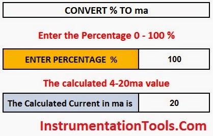
    Be careful this is for 4~20 ma not for fieldbus .

    Reply
    • S Bharadwaj Reddy says:
      December 1, 2015 at 6:52 am

      Dear Rahim, Thank you for the suggestions.

      Reply
    • Hadi says:
      November 20, 2017 at 5:00 am

      What’s the right way to re-range DP fieldbus “FF” transmitter?

      Reply
  • Raju says:
    December 23, 2015 at 5:32 am

    Sir,
    I Need Suggestion on Flow. Orifice D/P To Connected DP Transmitter With Sq.root Op.
    Indicator also Need Sq.root Input or Linier In put.

    Pls Explain sir.
    Regards
    Raju

    Reply
  • GANDHI says:
    May 16, 2016 at 5:41 am

    What is the minimum static working pressure

    Reply
  • Suresh badiger says:
    January 1, 2017 at 1:22 pm

    Sir I’m instrumentation Engg I have do transmitter in condensate water line as per data sheet 1500 mmwc I puted urv range in transmitter but I’m not getting full flow as per pump discharge 110 m/3 hr only I’m getting 49 m3/hr so please suggest

    Reply
  • jdp says:
    June 3, 2019 at 11:39 am

    if we re range the value… does the square root graph also change ?

    Reply
  • Saddam hussain says:
    March 5, 2020 at 8:04 pm

    Respected sir,
    Pls give me solution. How to we calculate nm3/hr flow for different case. Like air, gas. Please give one note with example.

    Reply
  • Le Huy Dat says:
    July 16, 2021 at 11:16 pm

    you can to chang for calibration range from 0 to 265 MPA with enering range from 0 to 10311.

    Reply
  • Cyrus says:
    June 19, 2022 at 8:02 pm

    Good day to all.
    I hope any one can help me elighten about Flow Transmitters. Why is it Flow transmitter has 2 ranges? Example process variable range from 0 to 2500 mmH2O and the other range (engineering range) is 0 to 160 t/h.

    Reply
  • GP says:
    August 21, 2024 at 4:32 pm

    We are plaining in-house calibration flow meters. would you please give me simple technique. How to set up and calibration step by step.

    Reply

Leave a Reply Cancel reply

Your email address will not be published. Required fields are marked *

Stay Connected

128.3kFollowersLike
69.1kFollowersFollow
210kSubscribersSubscribe
38kFollowersFollow

Categories

Explore More

Orifice Plate Tapping – Orifice Plate Taps
Metal Tube Variable Area Flow Meters Principle
Orifice Plate Turndown ratio
Volumetric Flow Calculations
Orifice Sizing Guidelines and Thumb Rules with Flowchart
Area Velocity Flow Meter Principle
What is a Torbar? – Averaging Pitot Tubes
Flow Meter Questions and Answers

Keep Learning

Boiler-Drum-Level-transmitter-calibration

Boiler Drum Level Transmitter Calibration

Ultrasonic Flow Meters Working Principle

Ultrasonic Flow Meters Working Principle

Flow Measurement Objective Questions

Flow Measurement Objective Questions

Venturi Flow Meter

Venturi Flow Meter – Working Principle, Advantages, Animation

Coriolis Mass Flow Meter Working Animation

Coriolis Meter Explained with Animation

Magnetic Flowmeter vs. Turbine Flowmeter

Magnetic Flowmeter vs. Turbine Flowmeter – Comparison

Flow Switch Principle

In-Line Flow Switch Working Principle and Animation

Electromagnetic Flow Meters Working Principle

Learn More

Digital Electronics Multiple Choice Questions

Parallel Adder and Subtractor Objective Questions

Automatic Packing of Bottles

Automatic Packing of Bottles Programming

What are Switchgear Interlocks?

What are Switchgear Interlocks?

Electrical Machines Questions and Answers

DC Generators Rotating Amplifiers Quiz

Purpose of End of Line (EOL) Resistor in Fire & Gas System ?

Why we use End of Line (EOL) Resistor in Fire and Gas System ?

Series Parallel Circuit Analysis

Series – Parallel Circuit Analysis

3 Phase Balanced Loads

Power in Balanced 3 Phase Loads

Electron Spin Resonance Questions & Answers

Basic ESR Spectrometer

Menu

  • About
  • Privacy Policy
  • Copyright

Quick Links

  • Learn PLC
  • Helping Hand
  • Part Time Job

YouTube Subscribe

Follow US
All rights reserved. Reproduction in whole or in part without written permission is prohibited.
Welcome Back!

Sign in to your account

Username or Email Address
Password

Lost your password?