DOL stands for Direct On-Line. The DOL starter is one of the types of Motor starter which connects the motor to the line voltages directly.
Contents
To start the induction motor in the simplest and cheapest way this type of starter is used.
In this type of starter, terminals of the motor are connected to the power supply through a contactor, circuit breaker, and protection device.
Components
Below is the list of components and devices used for the DOL starter wiring and circuit.
Protection Devices
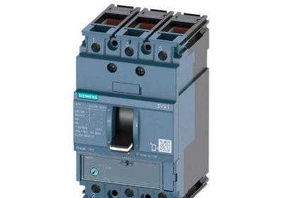
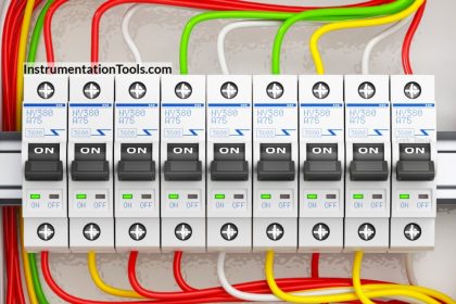
Miniature Circuit Breaker (MCB)
- This is an electromechanical device which switches off the circuit automatically if there is any irregularity function occurs.
- It is used for sensing the over-current caused by short circuit or any malfunction.
- It is an automatically operated electrical switch which are used for preventing damage to an electrical circuit as a result of excess current.
- It was designed in such a case to trip during an overload or short circuit to prevent against electrical faults and equipment failure
Overload Relay(OLR)
- This device is used to protect an electric motors against overloads and Phase failure.
- It also protects from phase loss , phase imbalance and overheating .
- So it is essential to have motor protection so that it can operated safely.
- This relay gets operated when current exceeds its preset value.
Control Devices
Contactor
- Contactor is an electrical device used to make or break a contact with a load , in simple terms it is used for switching an electrical circuit on or off.
- It is considered as a special type of relay.
- They are normally in open contact when energised it provides a operating power to the load.
- They are designed for carrying high current & the main part of the contactor is coil which is in inside of the contactor. The coil is also called as electromagnet.
Monitoring and auxiliary devices
Push Buttons
- Two push buttons were generally used in this starter . The were :
- NO (Normally Open) Push Button: It is a type of push button mainly used to start a circuit. In its default state ,it makes no contact with electrical circuit. When button is pressed, its state will be changed to closed contact and activates the electrical circuit.
- NC (Normally Close) Push Button: It is a type of push button mainly used to stop a circuit. In its default state ,it is in contact with electrical circuit. When button is pressed, its state will be changed to open contact and deactivates the electrical circuit.
Control Transformers
- Control transformer is a type of Isolation transformer which was useful where the available voltage must be converted to the required voltage. For example , from 230V to 24 V.
- It is designed as for stepping up/down and also for regulating the voltage as need.
- These reduced voltage provides a safer environment while working.
- They are also referred as power suppliers in some conditions.
Pilot Lamps
- They are also known as electrical indicator light that is usually used for indication purpose of any operation .
Measurement Devices
- These devices are mainly used for checking the given inputs were correct and the obtaining outputs were correct and also needed for the requirement.
- Mostly we want to measure two major factors , they are current and Voltage.
- Ammeter is used for measuring current and Voltmeter is used for measuring voltage.
- Ammeter is connected in series connection whereas Voltmeter is connected in parallel connection for getting the correct value.
- Nowadays, Multimeter or Clamp Multimeter where the devices for measuring current and voltages
DOL Starter Circuit Diagram
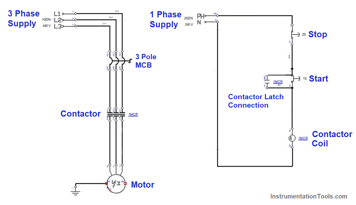
DOL Starter Working Principle
- The DOL Starter is started by simply pressing the Start Push button and stopped by pressing Stop push button. This method has easy way of controlling the device.
- If the push button is pressed, the contactor gets energised and gets closed. Even after the push button release also the contactor gets closed, because of the latching process. Now the motor is running smoothly without any problem.
- The motor is connected through normally closed auxiliary contact of Overload relay for protecting the motor from over-current. Whenever the over-current is passed, the overload trips.
- It makes auxiliary contact to open which de-energizes the contactor coil.
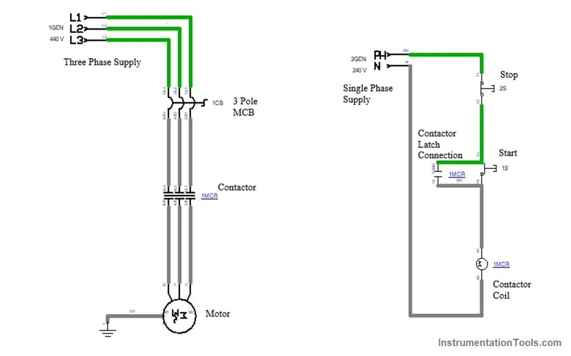
DOL Starter Explanation
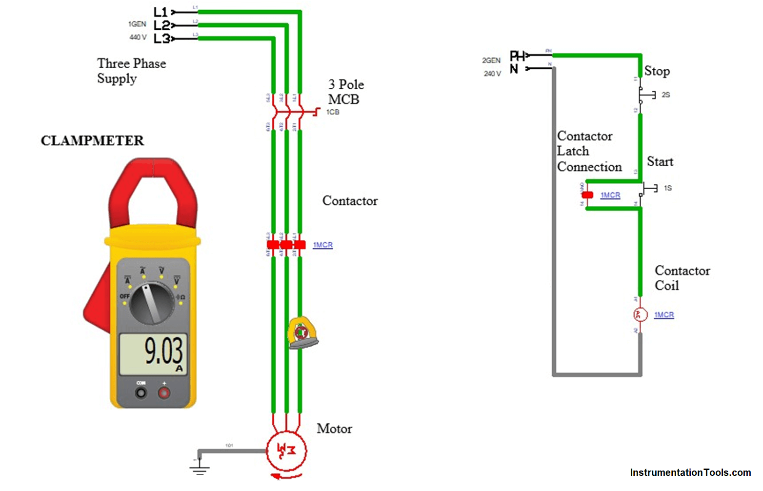
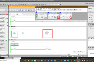
- When the Power supply is given, the main supply from both Power and Control circuit is started to pass in the circuit. The supply is indicated through Green Line
- Next turn on the MCB, which is used as Protection device to Protect the load from high Current. It is indicated in Red Colour in Below image.
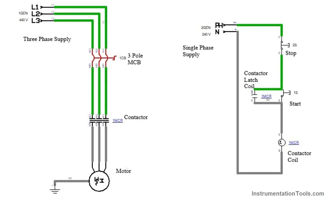
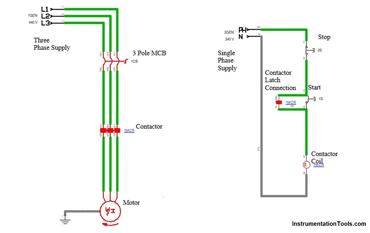
- Next to make the supply to the load (Motor) , the contactor should be on. Contactor gets energized by pressing the start push button in the Control Circuit.
- The control circuit has a single phase supply , which gives the supply to Contactor coil by using the Push buttons.
- Now, the contactor gets energized and holding connection of the contactor is given parallel in the control circuit.
- Thus the contactor gets energizes till the stop push button in the control circuit.
- We can measure the parameters (Current & Voltage) in this circuit by using multimeter and clamp meter.
- Multi-meter is used here for measuring Voltage and Clamp meter is used for measuring Voltage and Current here. Picture is given below for reference.
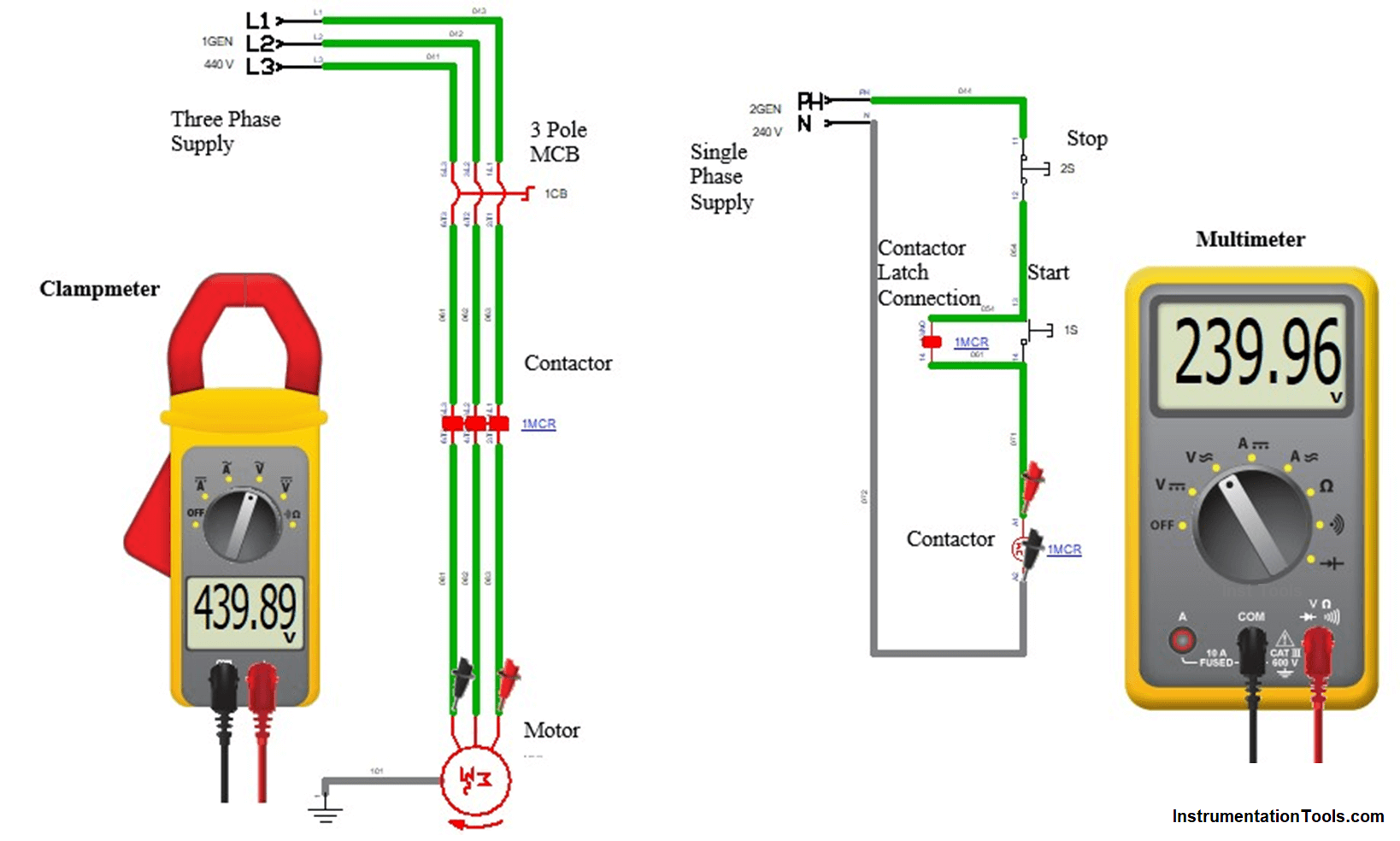
- In control circuit we measure the voltage by placing the two probes of Multi-meter in Phase and Voltage, We got the applied voltage which were shown in display.
- In Power Circuit, we used clamp-meter measuring Voltage and Current, Voltage is measured by placing the two probes in any two phase of supply ( for three measurement we want to place the probes in any two phase). Current is measured by the tong in the clamp meter by clipping in any one of the phase.
Advantages of DOL Starter
- It starts very quickly without any deviations
- Its cost is low compared to Star Delta and Soft Starter
- It can be implemented easily.
- Troubleshooting will be easy compared to other starters.
- Starting Torque is high
- Compact size
Disadvantages of DOL Starter
- Due to high starting current, it causes deviation in the power supply by dropping the voltages.
- High starting torque may cause damage to motor components.
- Only suitable for motor ranges up-to 5 HP.
Applications of DOL Starter
- It is very useful in motors with low HP rating.
- It is used where maximum currents do not cause any damage such as small compressors, conveyors, pumps, fans.


Very helpful information dol starter and auxiliary supply and electrical connections and components. Thank you so much sir.
good explanation