Some differential pressure transmitters are equipped with 5 way valve manifolds. These valve networks allow for blocking, equalizing, and bleeding of the transmitter’s two pressure ports, the valves being arranged in this pattern:
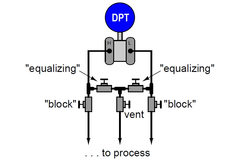
Shown using standard P&ID symbols – instrumentation equivalent of an electrical schematic diagram – the transmitter and manifold arrangement looks like this:
Identify the normal, operating valve positions (open/closed) for a five-valve manifold. Describe the proper sequence of manifold valve operation to successfully prepare the transmitter for removal from the process.
Why do you think we have such things as 5-valve manifolds? What can be done with this manifold that cannot be done with a three-valve manifold?
Restoring the transmitter back to service is as simple as reversing all the steps taken to remove it from service (i.e. go through the list backwards, doing the reverse of each instruction).
One feature that 5-valve manifolds provide over 3-valve manifolds is the ability to route a vent tube to a remote (safer) location, for use with particularly hazardous process fluids.
5-valve manifolds allow for in-place transmitter calibration, provided one of the ∆P transmitter’s sides has an atmospheric vent. By connecting the calibrating pressure source to the vent line, one can route the calibrating pressure to either side of the transmitter (only), while keeping the other side vented.
Share your answers with us through below comments section.
Read Next:
Credits: Tony R. Kuphaldt
Learn an example PLC program to control a pump based on level sensors using ladder…
In the PLC timer application for security camera recording, when motion is detected then camera…
In this example, we will learn batch mixing with PLC ladder logic program using timer…
This PLC example on manufacturing line assembly is an intermediate-level PLC program prepared for the…
In this article, you will learn the PLC programming example with pushbutton and motor control…
This article teaches how to convert Boolean logic to PLC programming ladder logic with the…


View Comments
Dear sir,
How to calibrate or zeroing of DPT with 5-way manifold.