Inst ToolsInst ToolsInst Tools
  • Ask
  • Courses
  • Videos
  • Q & A
    • Interview
      • Instrumentation
      • Electronics
      • Electrical
      • Practical Questions
    • MCQ
      • Instrumentation MCQ
      • Electrical MCQ
      • Electronics MCQ
      • Control Systems MCQ
      • Analog Electronics MCQ
      • Digital Electronics MCQ
      • Power Electronics MCQ
      • Microprocessor MCQ
      • Multiple Choice Questions
  • EE
    • Electronics
      • Electronics Q & A
      • Electronic Basics
      • Electronic Devices & Circuits
      • Electronics Animation
      • Digital Electronics
    • Electrical
      • Electrical Basics
      • Electrical Q & A
      • Power Electronics
      • Electrical Machines
      • Electrical Animation
      • Power Systems
      • Switchgear & Protection
      • Transmission & Distribution
  • Measure
    • Control Valves
    • Calibration
    • Temperature
    • Pressure
    • Flow
    • Level
    • Analyzers
    • Switches
    • Vibration
    • Solenoid Valve
  • Control
    • PLC Tutorials
    • Control Systems
    • Safety Instrumented System (SIS)
    • Communication
    • Fire & Gas System
  • More
    • Design
    • Tools
    • Animation
    • Basics
    • Formulas
    • Standards
    • TextBooks
    • Common
    • Software
    • Excel Tools
    • Erection & Commissioning
    • Process Fundamentals
    • Videos
    • Books
Search
All rights reserved. Reproduction in whole or in part without written permission is prohibited.
Reading: Diagnosing Electric Motor Circuit
Share
Notification Show More
Font ResizerAa
Inst ToolsInst Tools
Font ResizerAa
  • Courses
  • PLC Tutorials
  • Control Systems
Search
  • Ask
  • Courses
  • Videos
  • Q & A
    • Interview
    • MCQ
  • EE
    • Electronics
    • Electrical
  • Measure
    • Control Valves
    • Calibration
    • Temperature
    • Pressure
    • Flow
    • Level
    • Analyzers
    • Switches
    • Vibration
    • Solenoid Valve
  • Control
    • PLC Tutorials
    • Control Systems
    • Safety Instrumented System (SIS)
    • Communication
    • Fire & Gas System
  • More
    • Design
    • Tools
    • Animation
    • Basics
    • Formulas
    • Standards
    • TextBooks
    • Common
    • Software
    • Excel Tools
    • Erection & Commissioning
    • Process Fundamentals
    • Videos
    • Books
Follow US
All rights reserved. Reproduction in whole or in part without written permission is prohibited.
Inst Tools > Blog > Practical Questions > Diagnosing Electric Motor Circuit

Diagnosing Electric Motor Circuit

Last updated: January 8, 2020 2:41 pm
Editorial Staff
Practical Questions
No Comments
Share
2 Min Read
SHARE

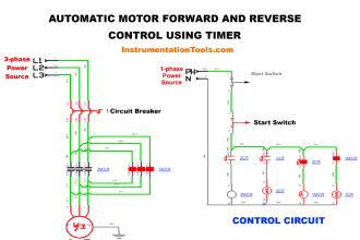
Suppose the electric motor refuses to run when the “Run” pushbutton switch is pressed. A technician begins diagnosing electric motor circuit following the steps shown (in order):

Contents
Diagnosing Electric Motor CircuitSolution:Read Next:
  • Test 1: Measured 12 volts DC between points C and D, with “Run” switch pressed.
  • Test 2: Measured 0 volts DC between points A and C, with “Run” switch unpressed.
  • Test 3: Measured 12 volts DC between points A and B, with “Run” switch pressed.
  • Test 4: Measured 12 volts DC between points E and F, with “Run” switch pressed.
  • Test 5: Measured infinite ohms between points E and F, with “Run” switch unpressed.

Diagnosing Electric Motor Circuit

Diagnosing the Electric Motor Circuit

Identify any useful information about the nature or location of the fault derived from the results of each test, in order of the tests performed.

If the test is not useful (i.e. provides no new information), mark it as such. Assuming there is only one fault in the circuit, identify the location and nature of the fault as precisely as you can from the test results shown above.

Solution:

The fault is an “open,” between points E and F.

Share your answers & explanations.

Credits: Tony R. Kuphaldt

Read Next:

  • AC Motor Theory
  • Types of AC Generators
  • AC Generation Analysis
  • Series-Wound Motor
  • DC Generator Internal Losses
Don't Miss Our Updates
Be the first to get exclusive content straight to your email.
We promise not to spam you. You can unsubscribe at any time.
Invalid email address
You've successfully subscribed !
Determine Resistance value of Resistors
How a Bourdon Tube Pressure Gauge might be Adjusted for Linearity?
Practical Process Control System Questions & Answers – 8
Pressure Gauge with Block and Bleed Valves
Draw the appropriate Pressure Switch Symbol ?
Share This Article
Facebook Whatsapp Whatsapp LinkedIn Copy Link
Share
Leave a Comment

Leave a Reply Cancel reply

Your email address will not be published. Required fields are marked *

Stay Connected

128.3kFollowersLike
69.1kFollowersFollow
208kSubscribersSubscribe
38kFollowersFollow

Categories

Recent Comments

  • Guifty Shimica on Top Non-PLC Certification Courses for Automation Professionals
  • Guifty Shimica on Top Non-PLC Certification Courses for Automation Professionals
  • MIHARITSOA Aina Sitraka on Top Non-PLC Certification Courses for Automation Professionals
  • Vaishnavi on Free Instrumentation Course for Trainee Engineers

Related Articles

Remote Seal Pressure Transmitter

How much Pressure will Remote Seal Pressure Transmitter Indicate?

Siemens PLC Questions

Programmable Logic Controller (PLC) Questions and Answers – 11

Current-to-Pressure Transducer Calibration Table

Galileo thermometer Principle

Galileo Thermometer

Float-type Level Switch for Sensing Low Oil Level

Float-type Level Switch for Sensing Low Oil Level

Span of Pressure Gauge

How to Decrease Span of Pressure Gauge?

solenoid valves trip

Identify Solenoid Valves Energized or de-energized?

Relay ladder diagram example

How to Draw a Schematic Diagram ?

More Articles

Manchester encoding

Foundation Fieldbus Electrical Parameters

Unstable & Drifting Values of Differential Pressure Transmitter

Unstable & Drifting Values of Differential Pressure Transmitter Problem

Feedback Characteristics of Control Systems

Feedback and Non-feedback Systems Objective Questions

Fire Damper

Fire Dampers in Fire Protection

Diaphragm valves

Basics of Valves

Root Cause Analysis for Valve Problem

Root Cause Analysis for Tank Overflow due to Valve Problem

CNC Machining vs 3D Printer

CNC Machining vs 3D Printer – What is the difference?

Statement List (STL) to Find Highest Value in the Data Block

Statement List (STL) to Find Highest Value

Follow US
All rights reserved. Reproduction in whole or in part without written permission is prohibited.
Welcome Back!

Sign in to your account

Username or Email Address
Password

Lost your password?