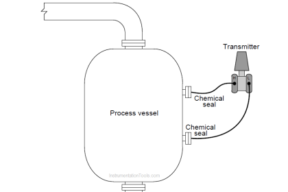
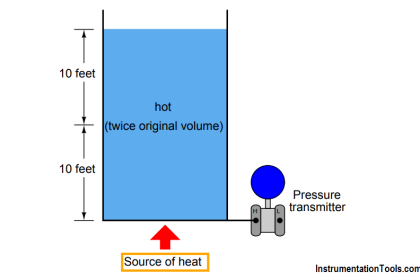
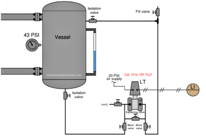
The following storage vessel holds water. A pneumatic pressure transmitter located at the bottom infers water level by hydrostatic pressure (head).
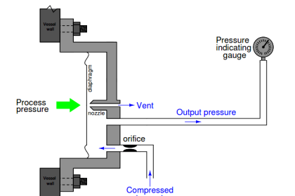
Pneumatic Pressure Transmitter
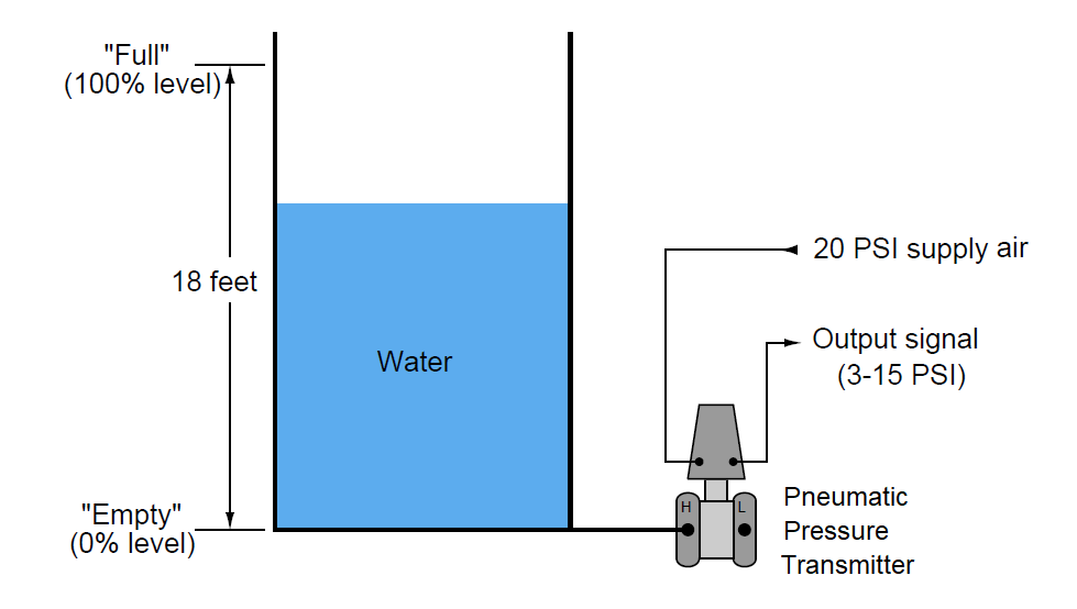
Determine the calibration range of this pressure transmitter in order to properly translate the range of vessel level (0 to 18 feet) into an output signal of 3 to 15 PSI.
Please express the transmitter’s calibration range in units of inches W.C. (inches of water column).
Then, determine the following (assuming the transmitter has been properly calibrated for the application):
Transmitter output signal (PSI) at 12 feet of level.
Water level at 5.9 PSI signal output.
Answer:
Lower range-values (LRV): 0 inches W.C. input = 3 PSI output
Upper range-values (URV): 216 inches W.C. input = 15 PSI output
Transmitter output signal (PSI) at 12 feet of level = 11 PSI
Water level at 5.9 PSI signal output = 4.35 feet
Note: Pneumatic pressure transmitters are outdated and these are replaced with electronic smart transmitters. These are discussed for educational purpose only.
Share your answers & explanation with us through the below comments section.
Read Next:
- Inferential Measurement
- Notes on Instrument Ranging
- Liquid Level Equilibrium
- Pneumatic DP Transmitter
- Hydrostatic Pressure Measurement
Credits: Tony R. Kuphaldt