Inst ToolsInst ToolsInst Tools
  • Courses
  • Automation
    • PLC
    • Control System
    • Safety System
    • Communication
    • Fire & Gas System
  • Instrumentation
    • Design
    • Pressure
    • Temperature
    • Flow
    • Level
    • Vibration
    • Analyzer
    • Control Valve
    • Switch
    • Calibration
    • Erection & Commissioning
  • Interview
    • Instrumentation
    • Electrical
    • Electronics
    • Practical
  • Q&A
    • Instrumentation
    • Control System
    • Electrical
    • Electronics
    • Analog Electronics
    • Digital Electronics
    • Power Electronics
    • Microprocessor
  • Request
Search
  • Books
  • Software
  • Projects
  • Process
  • Tools
  • Basics
  • Formula
  • Power Plant
  • Root Cause Analysis
  • Electrical Basics
  • Animation
  • Standards
  • 4-20 mA Course
  • Siemens PLC Course
Reading: Definitions of Electrical Grounding
Share
Font ResizerAa
Inst ToolsInst Tools
Font ResizerAa
  • Courses
  • Design
  • PLC
  • Interview
  • Control System
Search
  • Courses
  • Automation
    • PLC
    • Control System
    • Safety System
    • Communication
    • Fire & Gas System
  • Instrumentation
    • Design
    • Pressure
    • Temperature
    • Flow
    • Level
    • Vibration
    • Analyzer
    • Control Valve
    • Switch
    • Calibration
    • Erection & Commissioning
  • Interview
    • Instrumentation
    • Electrical
    • Electronics
    • Practical
  • Q&A
    • Instrumentation
    • Control System
    • Electrical
    • Electronics
    • Analog Electronics
    • Digital Electronics
    • Power Electronics
    • Microprocessor
  • Request
Follow US
All rights reserved. Reproduction in whole or in part without written permission is prohibited.
Inst Tools > Blog > Control Systems > Definitions of Electrical Grounding

Definitions of Electrical Grounding

Last updated: November 13, 2019 9:42 am
Editorial Staff
Control Systems
No Comments
Share
6 Min Read
SHARE

Definitions of Electrical Grounding

Definitions of Electrical Grounding

Contents
Definitions of Electrical GroundingAir Terminal:Bonding:Bonding Conductor:Bonding Jumper:Bonding Jumper, Main:Current-Carrying Part:Earth:Earth Electrode:Earthing Conductor:Earthing Network:Ground:Ground Grid:Ground terminal:Grounded:Grounded Conductor:Grounded, Effectively:Grounding Conductor:Grounding Conductor, Equipment:Grounding Electrode Conductor:Lightning Protection System:Main Earthing Terminal:Minimum Approach Distance:Neutral Conductor (N):Raceway:

Air Terminal:

That component of a lightning protection system that is intended to intercept lightning flashes, (commonly known as lightning rod).

Bonding:

The permanent joining of metallic parts to form an electrically conductive path that will ensure electrical continuity and the capacity to conduct safely any current likely to be imposed.

An electrical connection between an electrically conductive object and a component of a lightning protection system that is intended to significantly reduce potential differences created by lightning currents.

Bonding Conductor:

A conductor intended to be used for potential equalization between grounded metal boxes and the lightning protection system.

Bonding Jumper:

A reliable conductor to ensure the required electrical conductivity between metal parts required to be electrically connected.

Bonding Jumper, Main:

The connection between the grounded circuit conductor (neutral) and the equipment grounding conductor at the service.

Current-Carrying Part:

A conducting part intended to be connected in an electrical circuit to a source of voltage. Noncurrent-carrying parts are those not intended to be so connected.

Earth:

The conductive mass of the earth, whose electric potential at any point is conventionally taken as equal to zero. (In some countries the term “ground” is used instead of “earth”.

Earth Electrode:

A conductive part or a group of conductive parts in intimate contact with and providing an electrical connection with earth.

Earthing Conductor:

A protective conductor connecting the main earthing terminal or bar to the earth electrode. (Also see grounding electrode conductor.)

Earthing Network:

The part of an earthing installation that is restricted to the earth electrodes and their interconnections.

Ground:

A conducting connection, whether intentional or accidental, between an electrical circuit or equipment and the earth, or to some conducting body that serves in place of the earth.

Ground Grid:

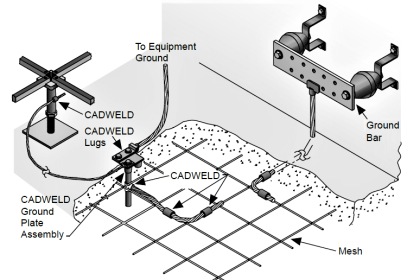
A system of grounding electrodes consisting of interconnected bare cables buried in the earth to provide a common ground.

Ground terminal:

The portion of the lightning protection system such as a ground rod, ground plate, or ground conductor, that is installed for the purpose of providing electrical contact with the earth.

Grounded:

Connected to earth or to some conducting body that serves in place of the earth.

Connected to earth or some conducting body that is connected to earth.

Grounded Conductor:

A system or circuit conductor that is intentionally grounded. (Also see Neutral Conductor.)

Grounded, Effectively:

Intentionally connected to earth through a ground connection or connections of sufficiently low impedance and having sufficient current-carrying capacity to prevent the buildup of voltages that may result in undue hazards to connected equipment or to persons.

Grounding Conductor:

A conductor used to connect equipment or the grounded circuit of a wiring system to a grounding electrode or electrodes

Grounding Conductor, Equipment:

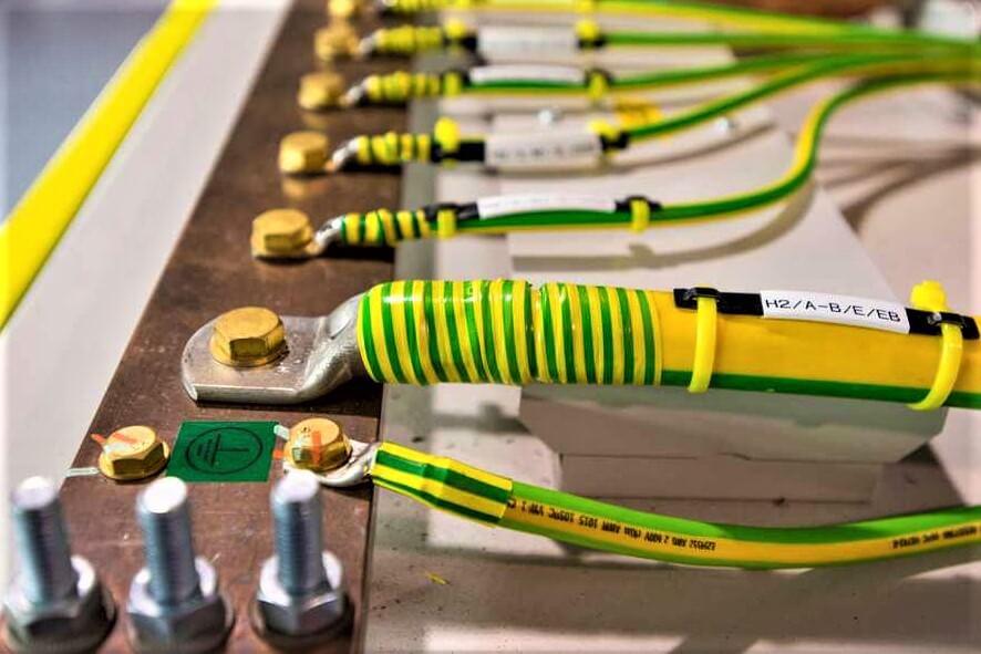
The conductor used to connect the noncurrent-carrying metal parts of equipment, raceways and other enclosures to the system grounded conductor, the grounding electrode conductor, or both, at the service equipment or at the source of a separately derived system. (Green wire)

Grounding Electrode Conductor:

The conductor used to connect the grounding electrode to the equipment grounding conductor, to the grounded conductor, or to both, of the circuit at the service equipment or at the source of a separately derived system. (Also see Earthing Conductor.)

Lightning Protection System:

A complete system of air terminals, conductors, ground terminals, interconnecting conductors, surge protection devices, and other connectors or fittings required to complete the system.

Main Earthing Terminal:

A terminal or bar provided for the connection of protective conductors including equipotential bonding conductors and conductors for functional earthing, if any, to the means of earthing.

Minimum Approach Distance:

The closest distance a qualified employee is permitted to approach either an energized or a grounded object, as applicable for the work method being used.

Neutral Conductor (N):

A conductor connected to the neutral point of a system and capable of contributing to the transmission of electrical energy. (Also see grounded conductor.)

Raceway:

Any channel designed expressly and used solely for holding conductors.

An enclosed channel of metal or nonmetallic materials designed expressly for holding wires, cables, or busbars, with additional functions as permitted in this Code. Raceways include, but are not limited to, rigid metal conduit, rigid nonmetallic conduit, intermediate metal conduit, liquid tight flexible conduit, flexible metallic tubing, flexible metal conduit, electrical nonmetallic tubing, electrical metallic tubing, cellular concrete floor raceways, cellular metal floor raceways, surface raceways, wireways, and busways.

Do you face any problems with grounding? Share with us.

Read Next:

  • Importance of Grounding Equipment
  • How to Avoid Bad Electrical Ground?
  • Induction Motors Faults and Protection
  • Telecommunication System Grounding
  • Components used in Electrical Ground
Don't Miss Our Updates
Be the first to get exclusive content straight to your email.
We promise not to spam you. You can unsubscribe at any time.
Invalid email address
You've successfully subscribed !

Continue Reading

Transmitters 4-20mA Current Failure Alarm Limits
Basics of Grounding
Identify Instruments in Piping and instrumentation Diagram
Explaining Various Types of Analog Instruments
How to Configure a Smart Transmitter Using a HART Communicator?
PLC Connection between Instrument, Junction Box, Marshalling & System Cabinet
Share This Article
Facebook Whatsapp Whatsapp LinkedIn Copy Link
Share
Leave a Comment

Leave a Reply Cancel reply

Your email address will not be published. Required fields are marked *

Stay Connected

128.3kFollowersLike
69.1kFollowersFollow
210kSubscribersSubscribe
38kFollowersFollow

Categories

Explore More

Capacitive Coupling Effects
What is an Electrical Drive? Types, Advantages, Disadvantages
VFD Commissioning and Testing Procedure (Variable Frequency Drive)
Instrumentation and Electrical Teams Interactions (Detail Design Engineering)
Integral (Reset) Control Theory
Loop-powered 4-20 mA Transmitter Circuit Voltage drop
Difference between ON-OFF Controller and PID Controller
What are AI, AO, DI, and DO? – Definition, Examples, Purpose

Keep Learning

Control Loop

What is a Control Loop ?

power factor correction equipment

Power Factor Controller (PFC) – Commissioning

PID Controller Responses to Two momentary step inputs

PID Controller Response with different Input Signals

Transducer

What is a Transducer ?

SC connector

What is a Network Connector? – Types of Connectors

Troubleshooting PLC Current Loops

Troubleshooting Current Loops with Voltage Measurement

Levels in Industrial Automation

Five Levels in Industrial Automation

Instrument Loop Diagram

How-to Create Instrument Loop Diagram (ILD)?

Learn More

Diode Rectifier

Bridge Rectifier Working Animation

YouTube Channels About Tech and Engineering

Awesome YouTube Channels About Tech and Engineering

absorption-type optical analyzer

Absorption Type Optical Analyzer

Digital Electronics Multiple Choice Questions

Design of Combinational Circuits Objective Questions

mass flowmeters

What is a Thermal Flow Meter?

7 OSI Layers of Communications

7 OSI Layers of Communication

Basic Electrical Engineering Interview Questions Answers

Basic Electrical Engineering Interview Questions Answers

What is Transformer Bushing

What is Transformer Bushing? Working Principle

Menu

  • About
  • Privacy Policy
  • Copyright

Quick Links

  • Learn PLC
  • Helping Hand
  • Part Time Job

YouTube Subscribe

Follow US
All rights reserved. Reproduction in whole or in part without written permission is prohibited.
Welcome Back!

Sign in to your account

Username or Email Address
Password

Lost your password?