Inst ToolsInst ToolsInst Tools
  • Courses
  • Videos
  • Q & A
    • Interview
      • Instrumentation
      • Electronics
      • Electrical
      • Practical Questions
    • MCQ
      • Instrumentation MCQ
      • Electrical MCQ
      • Electronics MCQ
      • Control Systems MCQ
      • Analog Electronics MCQ
      • Digital Electronics MCQ
      • Power Electronics MCQ
      • Microprocessor MCQ
      • Multiple Choice Questions
  • EE
    • Electronics
      • Electronics Q & A
      • Electronic Basics
      • Electronic Devices & Circuits
      • Electronics Animation
      • Digital Electronics
    • Electrical
      • Electrical Basics
      • Electrical Q & A
      • Power Electronics
      • Electrical Machines
      • Electrical Animation
      • Power Systems
      • Switchgear & Protection
      • Transmission & Distribution
  • Measure
    • Control Valves
    • Calibration
    • Temperature
    • Pressure
    • Flow
    • Level
    • Analyzers
    • Switches
    • Vibration
    • Solenoid Valve
  • Control
    • PLC Tutorials
    • Control Systems
    • Safety Instrumented System (SIS)
    • Communication
    • Fire & Gas System
  • More
    • Design
    • Tools
    • Animation
    • Basics
    • Formulas
    • Standards
    • TextBooks
    • Common
    • Software
    • Excel Tools
    • Erection & Commissioning
    • Process Fundamentals
    • Videos
    • Books
Search
All rights reserved. Reproduction in whole or in part without written permission is prohibited.
Reading: DC Motor Theory
Share
Notification Show More
Font ResizerAa
Inst ToolsInst Tools
Font ResizerAa
  • Courses
  • PLC Tutorials
  • Control Systems
Search
  • Courses
  • Videos
  • Q & A
    • Interview
    • MCQ
  • EE
    • Electronics
    • Electrical
  • Measure
    • Control Valves
    • Calibration
    • Temperature
    • Pressure
    • Flow
    • Level
    • Analyzers
    • Switches
    • Vibration
    • Solenoid Valve
  • Control
    • PLC Tutorials
    • Control Systems
    • Safety Instrumented System (SIS)
    • Communication
    • Fire & Gas System
  • More
    • Design
    • Tools
    • Animation
    • Basics
    • Formulas
    • Standards
    • TextBooks
    • Common
    • Software
    • Excel Tools
    • Erection & Commissioning
    • Process Fundamentals
    • Videos
    • Books
Follow US
All rights reserved. Reproduction in whole or in part without written permission is prohibited.
Inst Tools > Blog > Electrical Theory > DC Motor Theory

DC Motor Theory

Last updated: July 28, 2018 3:11 pm
Editorial Staff
Electrical Theory
No Comments
Share
5 Min Read
SHARE

DC motors are widely used to drive various equipment. The speed and torque produced in a DC motor depends on a variety of factors.

Inducing a Force on a Conductor

There are two conditions which are necessary to produce a force on a conductor.

  • The conductor must be carrying current.
  • The conductor must be within a magnetic field.

When these two conditions exist, a force will be applied to the conductor, which will attempt to move the conductor in a direction perpendicular to the magnetic field. This is the basic theory by which all DC motors operate.

Theory of Operation

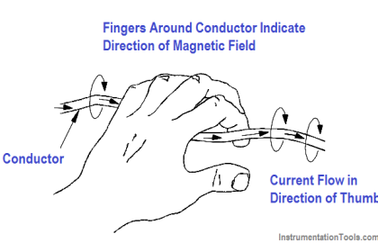
Every current-carrying conductor has a magnetic field around it. The direction of this magnetic field may be found by using the left-hand rule for current-carrying conductors. When the thumb points in the direction of current flow, the fingers will point in the direction of the magnetic field produced, as shown in Figure 1.

Left-Hand Rule for Current-Carrying Conductors

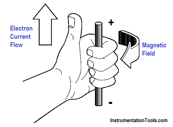
Figure 1 : Left-Hand Rule for Current-Carrying Conductors

If a current-carrying conductor is placed in a magnetic field, the combined fields will be similar to those shown in Figure 2. The direction of current flow through the conductor is indicated with an “x” or a “·”. The “x” indicates the current flow is away from the reader, or into the page. The “·” indicates the current flow is towards the reader, or out of the page.

Current-Carrying Conductor in a Magnetic Field

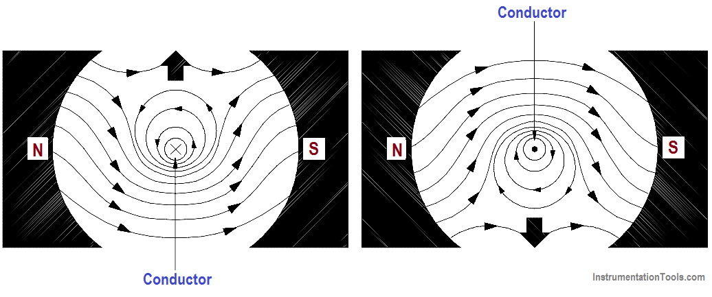
Figure 2 : Current-Carrying Conductor in a Magnetic Field

Above the conductor on the left, the field caused by the conductor is in the opposite direction of the main field, and therefore, opposes the main field. Below the conductor on the left, the field caused by the conductor is in the same direction as the main field, and therefore, aids the main field. The net result is that above the conductor the main field is weakened, or flux density is decreased; below the conductor the field is strengthened, or flux density is increased. A force is developed on the conductor that moves the conductor in the direction of the weakened field (upward).

Above the conductor on the right, the field caused by the conductor is in the same direction as the main field, and therefore, aids the main field. Below the conductor on the right, the field caused by the conductor is in the opposite direction of the main field, and therefore, opposes the main field. The net result is that above the conductor the field is strengthened, or flux density is increased, and below the conductor, the field is weakened, or flux density is decreased. A force is developed on the conductor that moves the conductor in the direction of the weakened field (downward).

In a DC motor, the conductor will be formed in a loop such that two parts of the conductor are in the magnetic field at the same time, as shown in Figure 3.

DC Motor Action

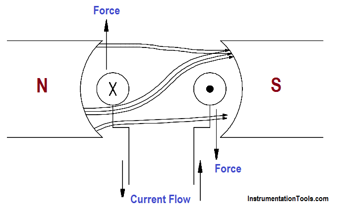
Figure 3 : Motor Action

This combines the effects of both conductors to distort the main magnetic field and produce a force on each part of the conductor. When the conductor is placed on a rotor, the force exerted on the conductors will cause the rotor to rotate clockwise, as shown on Figure 3.

You can think of these magnetic lines of force as rubber bands that are always trying to shorten themselves. The lines of force above the conductor exert a downward force due to the magnetic lines of force trying to straighten themselves.

The above explanation of how a force is developed is convenient; however, it is somewhat artificial. It is based on a fundamental principle of physics which may be stated as follows:

“A current-carrying conductor in a magnetic field tends to move at right angles to that field.”

Another important way to show the relationship between the current-carrying conductor, magnetic field, and motion, is the right-hand rule for motors, as shown in Figure 4.

Right-Hand Rule for Motors

Figure 4 : Right-Hand Rule for Motors

The right-hand rule for motors shows the direction in which a current-carrying conductor moves in a magnetic field. When the forefinger is pointed in the direction of the magnetic field lines, and the center finger is pointed in the direction of current flow, the thumb will point in the direction of force (motion).

Don't Miss Our Updates
Be the first to get exclusive content straight to your email.
We promise not to spam you. You can unsubscribe at any time.
Invalid email address
You've successfully subscribed !

Recommended Articles

Losses in AC Generator
Thermocouples
Block Diagram
Transformer Losses and Efficiency
Batteries
Reading Electrical Schematics
Share This Article
Facebook Whatsapp Whatsapp LinkedIn Copy Link
Share
Leave a Comment

Leave a Reply Cancel reply

Your email address will not be published. Required fields are marked *

Stay Connected

128.3kFollowersLike
69.1kFollowersFollow
208kSubscribersSubscribe
38kFollowersFollow

Categories

Recent Comments

  • William Snyder on Top Non-PLC Certification Courses for Automation Professionals
  • Kamli on Top Free PLC Software
  • Guifty Shimica on Top Non-PLC Certification Courses for Automation Professionals
  • Guifty Shimica on Top Non-PLC Certification Courses for Automation Professionals

Related Articles

Potential Difference Across a Conductor Causes a Current to Flow

Conductor, Insulator, Resistor and Current Flow

Motor Rotating Magnetic Field

AC Motor Theory

Transformer Operation Under No-Load

Transformer Operation Under No-Load

Simple RC Circuit

Impedance in RC Circuits

Split Phase Motor

Single Phase AC Induction Motors

Series - Wound DC Motor

Series-Wound Motor

Air Circuit Breaker Principle

High Voltage Circuit Breaker Principle

AC to DC Conversion with a Commutator

DC Machines Terminology

More Articles

Probability of failure on demand (PFD)

Probability of Failure on Demand (PFD)

Steam Eductor Question

A Series of False Pressure Alarms

Troubleshooting a Biased Transistor

Troubleshooting a Biased Transistor

Lead Acid Battery charge

Discharge and Charging of Lead-Acid Battery

orifice-plate

Orifice Plate Turndown ratio

What is a Time Delay Relay

What is a Time Delay Relay? Principle, Advantages, Disadvantages

Percentage-to-Process-Variable-Conversion

Formula for Percentage to Process Variable Conversion

Electrical Component Symbols

Electrical Diagrams and Schematics

Follow US
All rights reserved. Reproduction in whole or in part without written permission is prohibited.
Welcome Back!

Sign in to your account

Username or Email Address
Password

Lost your password?