Inst ToolsInst ToolsInst Tools
  • Courses
  • Automation
    • PLC
    • Control System
    • Safety System
    • Communication
    • Fire & Gas System
  • Instrumentation
    • Design
    • Pressure
    • Temperature
    • Flow
    • Level
    • Vibration
    • Analyzer
    • Control Valve
    • Switch
    • Calibration
    • Erection & Commissioning
  • Interview
    • Instrumentation
    • Electrical
    • Electronics
    • Practical
  • Q&A
    • Instrumentation
    • Control System
    • Electrical
    • Electronics
    • Analog Electronics
    • Digital Electronics
    • Power Electronics
    • Microprocessor
  • Request
Search
  • Books
  • Software
  • Projects
  • Process
  • Tools
  • Basics
  • Formula
  • Power Plant
  • Root Cause Analysis
  • Electrical Basics
  • Animation
  • Standards
  • 4-20 mA Course
  • Siemens PLC Course
Reading: Data Types in PLC – Bit, Byte, Integer, Real, String
Share
Font ResizerAa
Inst ToolsInst Tools
Font ResizerAa
  • Courses
  • Design
  • PLC
  • Interview
  • Control System
Search
  • Courses
  • Automation
    • PLC
    • Control System
    • Safety System
    • Communication
    • Fire & Gas System
  • Instrumentation
    • Design
    • Pressure
    • Temperature
    • Flow
    • Level
    • Vibration
    • Analyzer
    • Control Valve
    • Switch
    • Calibration
    • Erection & Commissioning
  • Interview
    • Instrumentation
    • Electrical
    • Electronics
    • Practical
  • Q&A
    • Instrumentation
    • Control System
    • Electrical
    • Electronics
    • Analog Electronics
    • Digital Electronics
    • Power Electronics
    • Microprocessor
  • Request
Follow US
All rights reserved. Reproduction in whole or in part without written permission is prohibited.
Inst Tools > Blog > PLC Tutorials > Data Types in PLC – Bit, Byte, Integer, Real, String

Data Types in PLC – Bit, Byte, Integer, Real, String

In this post, we will understand the various PLC data types like a bit, byte, integer, real, string, double integer, word, etc.

Last updated: December 23, 2023 10:16 am
Viral Nagda
PLC Tutorials
1 Comment
Share
5 Min Read
SHARE

In this post, we will understand the various PLC data types like a bit, byte, integer, real, string, etc.

Contents
Data Types in PLCBitByteIntegerDouble IntegerRealStringPLC Data Types Video

Various new programmers face issues in understanding a data type of PLC. Data type means the format of the variable or constant used in a program.

Data Types in PLC

Without understanding a data type and how its format works, a PLC programmer cannot develop and define a program properly.

Data Types in PLC

Bit

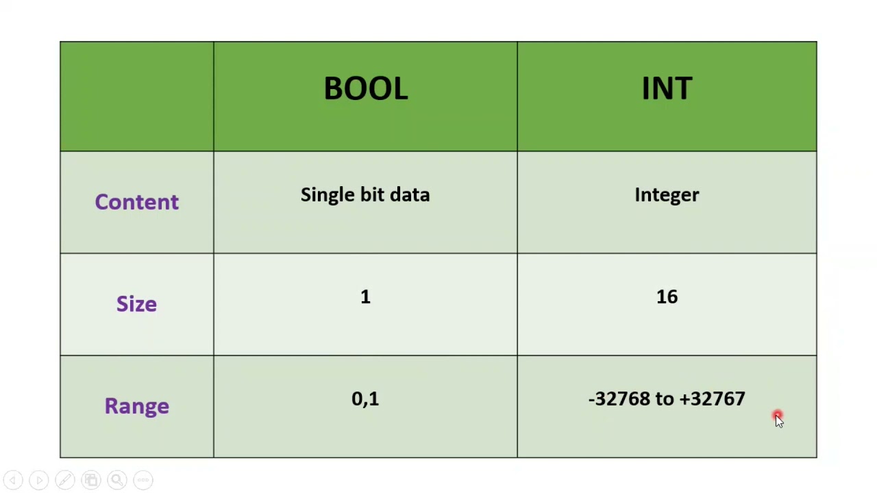
The format of a variable starts with a single bit. Its value is defined as 0 or 1.

In simpler terms, compare it with the Indian currency. It starts with a single paisa and multiple paisas make a rupee. Similarly, the format of any data type starts with a bit.

Its value is only true or false. The “bit” is also called as Boolean.

Byte

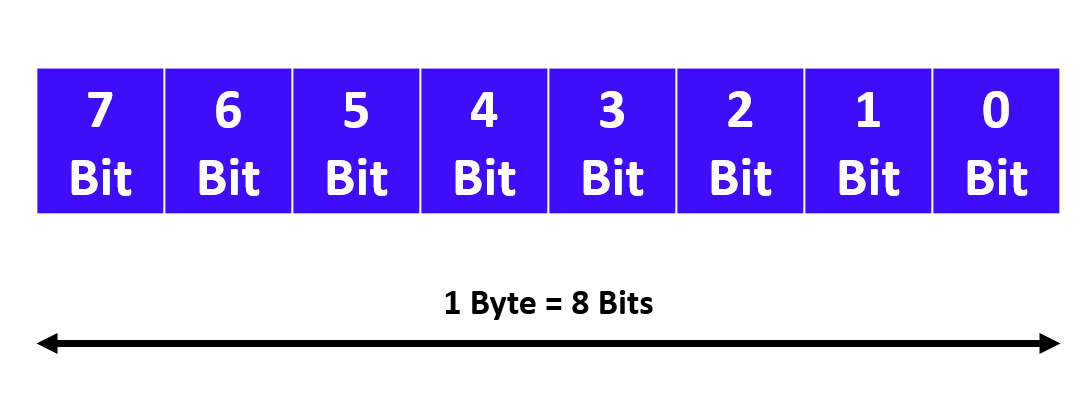
Now, 8 bits make a byte. The first start bit means LSB (least significant bit) and the last bit means MSB (most significant bit).

Refer to the below image. It comprises 8 number of bits, with each bit having its individual value. The range of a format is defined by 2n.

Here, n is the number of bits used in a data type.

So, as per the format used here in byte, the value for 28 will be 256. That means 256 numbers of combinations or values will be possible in a byte.

1 Byte

Any format with multiple bits can be classified into two types – signed and unsigned. Signed means the range has both positive and negative numbers.

Unsigned means the range has only positive numbers. So, here in a byte, an unsigned byte means 0 to 25; and a signed byte means -128 to 127.

 A byte is also called a short integer.

Integer

Now, 16 bits make an integer. The first start byte means LSB (least significant byte) and the last byte means MSB (most significant byte).

The value for 216 will be 65536. That means 65536 numbers of combinations or values will be possible in an integer.

An integer is also called as a word. But, a word cannot be signed. It will be unsigned only.

An unsigned integer means 0 to 65535, and a signed integer means -32768 to 32767.

Double Integer

Now, 32 bits make a double integer. The value for 232 will be 4294967296. That means 4294967296 numbers of combinations or values will be possible in a double integer.

An unsigned double integer means 0 to 4294967296, and a signed double integer means -2147483648 to 2147483647.

In a PLC memory, two words make a double integer. So, for example, consider a Schneider PLC. %MW0 and %MW1 both will make a double integer; whereas only a single %MW0 or %MW1 will make an integer.

So, if you use %MD0 in this PLC, the next available address will be %MD2; as %MD0 comprises of %MW0 and %MW1.

Real

Here too, 32 bits makes a real format. But, the major difference between real and double integers is that a real variable can directly be assigned a decimal value.

The value will be from -3.4028235E+38 to 3.4028235E+38.

Like a double integer, a real format also uses two memory words.

String

A string format can contain any string of characters – numeric or alphanumeric. Every PLC has its own reserved memory for string variables.

The memory space needed for a string is 1 byte per character + 1 additional byte.

So, say a value – WELCOME. It will require 7 bytes for storing this value plus one additional byte; which means a total of 8 bytes will be required.

These are some of the generally used data types in a PLC.

PLC Data Types Video

In the below video, we discussed the various types of data in Omron PLC.

Data Types in CX Programmer - Omron PLC Programming Tutorial (Hindi)

If you liked this article, then please subscribe to our YouTube Channel for Instrumentation, Electrical, PLC, and SCADA video tutorials.

You can also follow us on Facebook and Twitter to receive daily updates.

Read Next:

  • Validate PLC Inputs
  • PLC Best Practices
  • What is Hot Standby in PLC?
  • Monitor PLC Memory Usage
  • Converter in Siemens PLC
Don't Miss Our Updates
Be the first to get exclusive content straight to your email.
We promise not to spam you. You can unsubscribe at any time.
Invalid email address
You've successfully subscribed !

Continue Reading

Elevator PLC Ladder Logic
PLC Programming for 3 Motors control in Ladder logic
Example of Controlling the PLC Output using Push Buttons
Applications of SCADA
#20 PLC Best Practices – Identify Critical Alerts
GET Command – Siemens PLC-to-PLC Communication Project
Share This Article
Facebook Whatsapp Whatsapp LinkedIn Copy Link
Share
1 Comment
  • shreyas shendage says:
    June 22, 2023 at 10:45 am

    Nice and interesting topics

    Reply

Leave a Reply Cancel reply

Your email address will not be published. Required fields are marked *

Stay Connected

128.3kFollowersLike
69.1kFollowersFollow
210kSubscribersSubscribe
38kFollowersFollow

Categories

Explore More

Tia Portal – OB30 Cyclic Interrupt Organization Block
Using Clock Memory Bits in TIA Portal – Siemens PLC
Learn about SCADA and HMI Systems
Structured Text PLC Programming for Two-Tanks Level Application
Concept of Interlocking in PLC
Components of PLC
Best 100 PLC Projects for Final Year Engineering Students
DCS Commissioning Steps

Keep Learning

Real-time PLC Projects

Real-time PLC Projects – Industrial Automation

Industrial Gas Detection Systems

PLC based Gas Detection System using Ladder Logic Project

Sorting Defective Parts PLC Logic

Advanced PLC Programming for Defective Parts Sorting

Siemens Simatic HMI

How to Design an Effective HMI? – Human Machine Interface

PLC Latching circuit Animation

What is Seal-in Circuit ?

Brands PLC communication interface and protocol

Communicating Between Siemens PLC and Other PLC Brands

Electrical Ladder Diagram Control using Timers Example

Electrical Ladder Diagram Control using Timers Example

ON and OFF a Group of Outputs by One Push button PLC Logic

ON and OFF a Group of Outputs by One Push button PLC Logic

Learn More

Electronic Devices & Circuits Objective Questions

Electronic Devices & Circuits Quiz – Set 11

Feedback Characteristics of Control Systems

Feedback and Non-feedback Systems Objective Questions

Electrical Machines Questions and Answers

Rotating Magnetic Field Multiple Choice Questions

3-Wire, Three-Phase Delta Wiring System

3-Wire, Three-Phase Delta Wiring System

7 OSI Layers of Communications

7 OSI Layers of Communication

InTouch SCADA Training Course

Free InTouch SCADA Tutorial Course for Beginners

Fundamental Motion Control Commands

Fundamental Motion Control Commands

circuit-breaker-interview-questions-answers

Circuit Breaker Interview Questions & Answers

Menu

  • About
  • Privacy Policy
  • Copyright

Quick Links

  • Learn PLC
  • Helping Hand
  • Part Time Job

YouTube Subscribe

Follow US
All rights reserved. Reproduction in whole or in part without written permission is prohibited.
Welcome Back!

Sign in to your account

Username or Email Address
Password

Lost your password?