Inst ToolsInst ToolsInst Tools
  • Courses
  • Automation
    • PLC
    • Control System
    • Safety System
    • Communication
    • Fire & Gas System
  • Instrumentation
    • Design
    • Pressure
    • Temperature
    • Flow
    • Level
    • Vibration
    • Analyzer
    • Control Valve
    • Switch
    • Calibration
    • Erection & Commissioning
  • Interview
    • Instrumentation
    • Electrical
    • Electronics
    • Practical
  • Q&A
    • Instrumentation
    • Control System
    • Electrical
    • Electronics
    • Analog Electronics
    • Digital Electronics
    • Power Electronics
    • Microprocessor
  • Request
Search
  • Books
  • Software
  • Projects
  • Process
  • Tools
  • Basics
  • Formula
  • Power Plant
  • Root Cause Analysis
  • Electrical Basics
  • Animation
  • Standards
  • 4-20 mA Course
  • Siemens PLC Course
Reading: Current to Pressure (I/P) Converter Principle
Share
Font ResizerAa
Inst ToolsInst Tools
Font ResizerAa
  • Courses
  • Design
  • PLC
  • Interview
  • Control System
Search
  • Courses
  • Automation
    • PLC
    • Control System
    • Safety System
    • Communication
    • Fire & Gas System
  • Instrumentation
    • Design
    • Pressure
    • Temperature
    • Flow
    • Level
    • Vibration
    • Analyzer
    • Control Valve
    • Switch
    • Calibration
    • Erection & Commissioning
  • Interview
    • Instrumentation
    • Electrical
    • Electronics
    • Practical
  • Q&A
    • Instrumentation
    • Control System
    • Electrical
    • Electronics
    • Analog Electronics
    • Digital Electronics
    • Power Electronics
    • Microprocessor
  • Request
Follow US
All rights reserved. Reproduction in whole or in part without written permission is prohibited.
Inst Tools > Blog > Control Valves > Current to Pressure (I/P) Converter Principle

Current to Pressure (I/P) Converter Principle

Last updated: March 21, 2019 4:55 pm
Editorial Staff
Control Valves
1 Comment
Share
2 Min Read
SHARE

Current to Pressure Converter works on flapper nozzle method. The input is 4 to 20mA signal and the equivalent output is 3 to 15 PSI pressure.

Also Read : What is Flapper/Nozzle System

Current to Pressure Converter
Current to Pressure Converter Principle

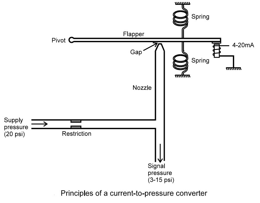
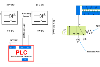
In the Current to Pressure converter, we usually give input current signal as 4 – 20 mA .  We also give a continuous supply of 20 P.S.I to the Flapper Nozzle assembly. As we give input current signal, Electromagnet gets activated.

If the current is more, then the power of magnet will get increased. The Flapper of the Flapper-Nozzle instrument is connected to Pivot so that it can move up and down and a magnetic material was attached to other end of flapper and it is kept near the electromagnet.

As the magnet gets activated. the flapper moves towards the electromagnet and the nozzle gets closed to some extent. So the some part of 20 P.S.I supplied will escape through nozzle and remaining pressure will come as output.

If the current signal is high, then power of the magnet will increase, then flapper will move closer to the nozzle, so less pressure will escape through nozzle and output pressure increases.

In this way the output pressure will be proportional to the input current.

For the input current of 4 – 20 mA we can get the output pressure of 3 – 15 P.S.I

Articles You May Like :

Control Valve Volume Booster

Pressure Transmitter Tips

4-20ma from Process variable

Pneumatic Load Cell Principle

PLC Temperature Control

Don't Miss Our Updates
Be the first to get exclusive content straight to your email.
We promise not to spam you. You can unsubscribe at any time.
Invalid email address
You've successfully subscribed !

Continue Reading

Metal Seated Valves and Soft Seated Valves : Differences
Directional Control Valves Working Principle
Calculate Flow Coefficient Kv of Solenoid Valve
How Ball Valves Work ?
Control Valve Working Animation
What is a Spool Valve? – Types, Configurations, Applications
Share This Article
Facebook Whatsapp Whatsapp LinkedIn Copy Link
Share
1 Comment
  • Rohit Sihotra says:
    June 24, 2020 at 9:44 pm

    ?

    Reply

Leave a Reply Cancel reply

Your email address will not be published. Required fields are marked *

Stay Connected

128.3kFollowersLike
69.1kFollowersFollow
210kSubscribersSubscribe
38kFollowersFollow

Categories

Explore More

How to Do Maintenance of Control Valve Which is Stuck in Field?
Pilot-operated Relief Valve Principle
Digital Control Valve Working Principle
Types of Check Valves
What is Double-ported Globe Valve ?
Pneumatic Valves Questions & Answers
Complementary Control Valve Sequence
Progressive Control Valve Sequence

Keep Learning

Complementary Split Range Control

What is Complementary Split Range Control (CSRC)?

Gate Valve

How Gate Valves Work ?

Rotary Stem Valves

Rotary Stem Valves

PISTON CHECK VALVE THEORY

Valve Materials Comparison Notes

Dual Solenoid Valve on Control Valve

Why we Require Dual SOV on a Control Valve?

Special Control Valves

Special Control Valves

Butterfly check valves

What is Butterfly Check Valve ?

Safety Relief Valve Questions & Answers

Safety Relief Valve Questions & Answers

Learn More

Caliper Calibration

Setting Up for Success: Preparing for Caliper Calibration

Heat Exchanger Baffles Holes

Heat Exchanger Tubes Corroded Root Cause Analysis

Units of Electrical Measurement

Units of Electrical Measurement

Benefits of Pursuing a Degree in Engineering

Benefits of Pursuing a Degree in Engineering

Boiler Blowdown

What is Boiler blowdown ?

Off load Tap Changer Principle

Transformer Tap Changing Working Principle

Power Electronics Objective Questions

1 Phase Voltage Source Inverter Quiz

Instrumentation Thread

Thread Sealant Types and Selection for Instrumentation Applications

Menu

  • About
  • Privacy Policy
  • Copyright

Quick Links

  • Learn PLC
  • Helping Hand
  • Part Time Job

YouTube Subscribe

Follow US
All rights reserved. Reproduction in whole or in part without written permission is prohibited.
Welcome Back!

Sign in to your account

Username or Email Address
Password

Lost your password?