Coriolis flow meters represent the state-of-the-art in mass flow measurement. While incredibly versatile and accurate, their internal operation can be difficult to understand.
Coriolis Flow Meter
Put into very simple terms, a Coriolis flow meter works by shaking one or more tubes carrying the flowing fluid, then precisely measuring the frequency and phase of that shaking.
The back-and-forth shaking is driven by an electromagnetic coil, powered by an electronic amplifier circuit to shake the tube(s) at their mechanical resonant frequency.
Since this frequency depends on the mass of each tube, and the mass of the tubes depends on the density of the fluid filling the fixed volume of the tubes, the resonant frequency becomes an inverse indication of fluid density (Note 1), whether or not fluid is flowing through the tubes.
As fluid begins to move through the tubes, the inertia of the moving fluid adds another dimension to the tubes’ motion: the tubes begin to undulate (Note 2), twisting slightly instead of just shaking back and forth.
This twisting motion is directly proportional to the mass flow rate, and is internally measured by comparing the phase shift (θ) between motion at one point on the tube versus another point on the tube: the greater the undulation, the greater the phase shift between these two points’ vibrations.
Note 1: In fact, this density-measuring function of Coriolis flow meters is so precise that they often find used primarily as density meters, and only secondarily as flow meters!
Note 2: An interesting experiment to perform consists of holding a water hose in a U-shape and gently swinging the hose back and forth like a pendulum, then flowing water through that same hose while you continue to swing it. The hose will begin to undulate, its twisting motion becoming visually apparent.

The Coriolis Force
In physics, certain types of forces are classified as fictitious or pseudo forces because they only appear to exist when viewed from an accelerating perspective (called a non-inertial reference frame).
The feeling you get in your stomach when you accelerate either up or down in an elevator or when riding a roller-coaster at an amusement park feels like a force acting against your body when it is really nothing more than the reaction of your body’s inertia to being accelerated by the vehicle you are in.
The real force is the force of the vehicle against your body, causing it to accelerate. What you perceive is merely a reaction to that force and not the primary cause of your discomfort as it might appear to be.
Centrifugal force is another example of a “pseudo force” because although it may appear to be a real force acting on any rotating object, it is in fact nothing more than an inertial reaction.
Centrifugal force is a common experience to any child who has ever played on a “merry-go-round:” that perception of a force drawing you away from the center of rotation, toward the rim.
The real force acting on any rotating object is toward the center of rotation (a centripetal force) which is necessary to make the object radially accelerate toward a center point rather than travel in a straight line as it normally would without any forces acting upon it. When viewed from the perspective of the spinning object, however, it would seem there is a force drawing the object away from the center (a centrifugal force).
Yet another example of a “pseudo force” is the Coriolis force, more complicated than centrifugal force, arising from motion perpendicular to the axis of rotation in a non-inertial reference frame.
The example of a merry-go-round works to illustrate Coriolis’s force as well: imagine sitting at the center of a spinning merry-go-round, holding a ball. If you gently toss the ball away from you and watch the trajectory of the ball, you will notice it curve rather than travel away in a straight line.
In reality, the ball is traveling in a straight line (as viewed from an observer standing on the ground), but from your perspective on the merry-go-round, it appears to be deflected by an invisible force which we call the Coriolis force.
In order to generate a Coriolis force, we must have a mass moving at a velocity perpendicular to an axis of rotation:
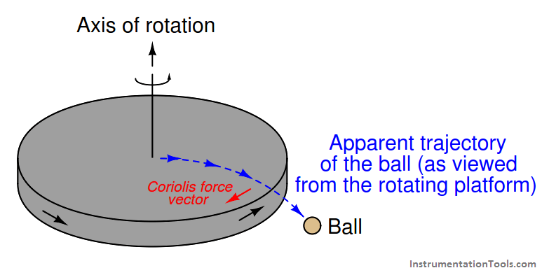
The magnitude of this force is predicted by the following vector equation :

If we replace the ball with a fluid moving through a tube, and we introduce a rotation vector by tilting that tube around a stationary axis (a fulcrum), a Coriolis force develops on the tube in such a way as to oppose the direction of rotation just like the Coriolis force opposed the direction of rotation of the rotating platform in the previous illustration:
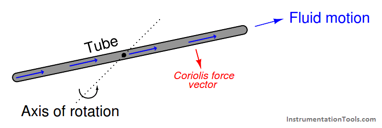
To phrase this in anthropomorphic terms, the fluid “fights” against this rotation because it “wants” to keep traveling in a straight line.
For any given rotational velocity, the amount of “fight” will be directly proportional to the product of fluid velocity and fluid mass. In other words, the magnitude of the Coriolis force will be in direct proportion to the fluid’s mass flow rate. This is the basis of a Coriolis mass flowmeter.
A demonstration of this Coriolis force may be made by modifying the nozzles on a rotary lawn sprinkler so they point straight out from the center rather than angle in one direction. As water squirts through the now-straight nozzles, they no longer generate a rotational reaction force to spin the nozzle assembly, and so the nozzles remain in place (this much should be obvious).
However, if someone were to try rotating the nozzle assembly by hand, they would discover the Coriolis force opposes the rotation, acting to keep the nozzle assembly from rotating.
The greater the mass flow rate of water through the nozzles, the stronger the inhibiting Coriolis force. Instead of a rotating lawn sprinkler, you are now the proud owner of an anti-rotating lawn sprinkler that actually fights any attempt to rotate it:
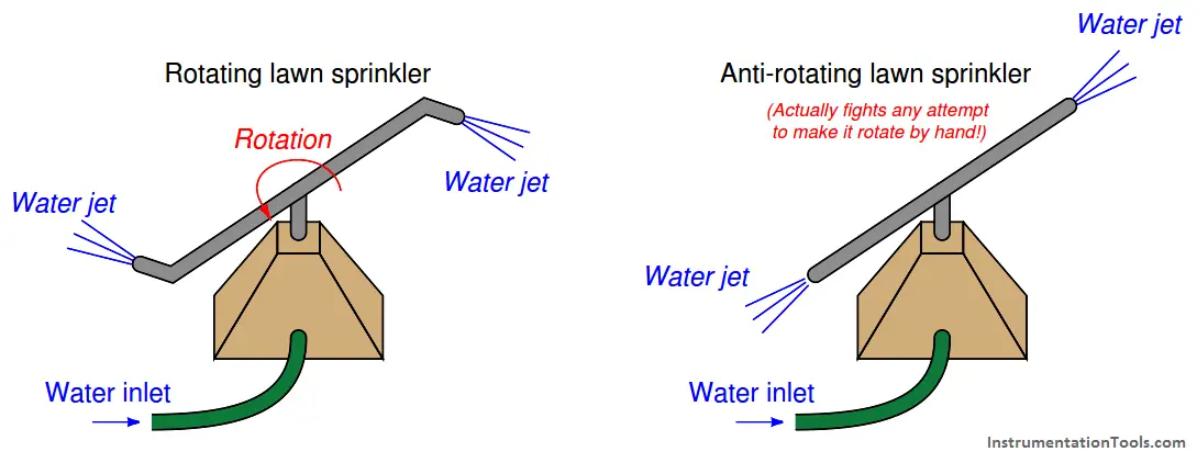
This is a very non-intuitive concept, so it deserves further explanation. The “anti-rotating” sprinkler doesn’t just fail to rotate on its own – it actually opposes any attempt to rotate from an external force (e.g. a person trying to push the tubes by hand).
This opposition would not occur if the tubes were merely capped off at the ends and filled with stagnant water. If this were the case, the tubes would simply be heavy with the water’s weight, and they would rotate freely about the axis just like any pair of heavy metal tubes would (whether hollow and filled with water, or solid metal). The tubes would have inertia, but they would not actively oppose any external effort to rotate.
Having liquid water move through the tubes is what makes the difference, and the reason becomes clear once we imagine what each water molecule experiences as it flows from the center (axis of rotation) to the nozzle at the tube tip.
Each water molecule originating from the center begins with no lateral velocity, but must accelerate as it travels farther along the tube toward the circumference of the tips’ rotation where the lateral velocity is at a maximum.
The fact that new water molecules are continually making this journey from center to tip means there will always be a new set of water molecules requiring acceleration from center velocity (zero) to tip velocity (maximum). In capped tubes filled with stagnant water, the acceleration would only occur in getting the tubes’ rotation up to speed – once there, the lateral velocity of each water molecule sitting stagnant inside the tubes would remain the same.
However, with water flowing from center to tip, this process of acceleration from zero velocity to tip velocity must occur over and over again (continually) for each new water molecule flowing through. This continual acceleration of new mass is what generates the Coriolis force, and what actively opposes any external force trying to rotate the “anti-rotating” sprinkler.
As you might guess, it can be difficult to engineer a tubing system capable of spinning in circles while carrying a flow stream of pressurized fluid. To bypass the practical difficulties of building a spinning tube system, Coriolis flow meters are instead built on the principle of a flexible tube that oscillates back and forth, producing the same effect in a cyclic rather than continuous fashion. The effect is not unlike shaking a hose (Note) side to side as it carries a stream of water:
Note: The Coriolis force generated by a flowing fire hose as firefighters work to point it in a different direction can be quite significant, owing to the high mass flow rate of the water as it flows through the hose and out the nozzle!
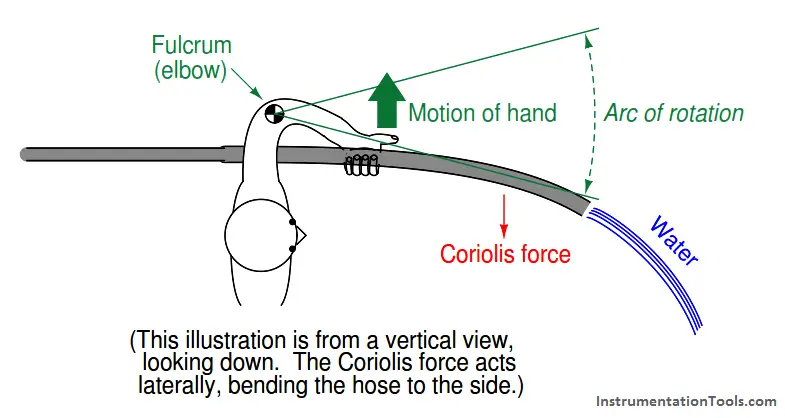
The Coriolis force opposes the direction of rotation. The greater the mass flow rate of water through the hose, the stronger the Coriolis force.
If we had a way to precisely measure the Coriolis force imparted to the hose by the water stream, and to precisely wave the hose so its rotational velocity held constant for every wave, we could directly infer the water’s mass flow rate.
If you liked this article, then please subscribe to our YouTube Channel for Instrumentation, Electrical, PLC, and SCADA video tutorials.
You can also follow us on Facebook and Twitter to receive daily updates.
Read Next:
- Mass Flow Sensor Theory
- Coriolis Flow Meter Inaccuracy
- Flow Proportional to Square Root of DP
- Coriolis Mass Multi Transmitter
- Insertion Flow Meter Theory
