All control valves have an inherent flow characteristics that defines the relationship between ‘valve opening’ and flowrate under constant pressure conditions.
Please note that ‘valve opening’ in this context refers to the relative position of the valve plug to its closed position against the valve seat. It does not refer to the orifice pass area.
The orifice pass area is sometimes called the ‘valve throat’ and is the narrowest point between the valve plug and seat through which the fluid passes at any time. For any valve, however it is characterised, the relationship between flowrate and orifice pass area is always directly proportional.
Valves of any size or inherent flow characteristic which are subjected to the same volumetric flowrate and differential pressure will have exactly the same orifice pass area.
However, different valve characteristics will give different ‘valve openings’ for the same pass area. Comparing linear and equal percentage valves, a linear valve might have a 25% valve opening for a certain pressure drop and flowrate, whilst an equal percentage valve might have a 65% valve opening for exactly the same conditions. The orifice pass areas will be the same.
Control Valve Characteristics
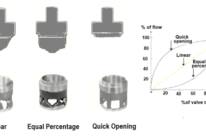
The physical shape of the plug and seat arrangement, sometimes referred to as the valve ‘trim’, causes the difference in valve opening between these valves. Typical trim shapes for spindle operated globe valves are compared in below figure-1.

In this Tutorial, the term ‘valve lift’ is used to define valve opening, whether the valve is a globe valve (up and down movement of the plug relative to the seat) or a rotary valve (lateral movement of the plug relative to the seat).
Rotary valves (for example, ball and butterfly) each have a basic characteristic curve, but altering the details of the ball or butterfly plug may modify this. The inherent flow characteristics of typical globe valves and rotary valves are compared in Figure.
Globe valves may be fitted with plugs of differing shapes, each of which has its own inherent flow/opening characteristic.
The three main types available are usually designated:
- Fast opening.
- Linear.
- Equal percentage.
Examples of these and their inherent characteristics are shown in below figure-2.

Fast opening characteristics
The fast opening characteristic valve plug will give a large change in flowrate for a small valve lift from the closed position. For example, a valve lift of 50% may result in an orifice pass area and flowrate up to 90% of its maximum potential.
A valve using this type of plug is sometimes referred to as having an ‘on / off’ characteristic.
Unlike linear and equal percentage characteristics, the exact shape of the fast opening curve is not defined in standards. Therefore, two valves, one giving a 80% flow for 50% lift, the other 90% flow for 60% lift, may both be regarded as having a fast opening characteristic.
Fast opening valves tend to be electrically or pneumatically actuated and used for ‘on / off’ control.
The self-acting type of control valve tends to have a plug shape similar to the fast opening plug in Figure .1. The plug position responds to changes in liquid or vapour pressure in the control system.
The movement of this type of valve plug can be extremely small relative to small changes in the controlled condition, and consequently the valve has an inherently high rangeability. The valve plug is therefore able to reproduce small changes in flowrate, and should not be regarded as a fast opening control valve.
Linear characteristics
The linear characteristic valve plug is shaped so that the flowrate is directly proportional to the valve lift (H), at a constant differential pressure.
A linear valve achieves this by having a linear relationship between the valve lift and the orifice pass area (see below Figure .3).

For example, at 40% valve lift, a 40% orifice size allows 40% of the full flow to pass.
Equal percentage characteristic (or logarithmic characteristic)
These valves have a valve plug shaped so that each increment in valve lift increases the flowrate by a certain percentage of the previous flow.
The relationship between valve lift and orifice size (and therefore flowrate) is not linear but logarithmic, and is expressed mathematically in below Equation
![]()
Where:
 = Volumetric flow through the valve at lift H
x = (ln t) H Note: ‘In’ is a mathematical function known as ‘natural logarithm’
t = Valve rangeability (ratio of the maximum to minimum controllable flowrate, typically 50 for a globe type control valve)
H = Valve lift (0 = closed, 1 = fully open)
max = Maximum volumetric flow through the valve
Example
The maximum flowrate through a control valve with an equal percentage characteristic is 10 m/h. If the valve has a turndown of 50:1, and is subjected to a constant differential pressure, by using Equation what quantity will pass through the valve with lifts of 40%, 50%, and 60% respectively?
Where:
t = Valve rangeability = 50
H = Valve lift (0 = closed, 1 = fully open) = 0.4; 0.5; 0.6
max = Maximum volumetric flow through the valve = 10 m/h

The increase in volumetric flowrate through this type of control valve increases by an equal percentage per equal increment of valve movement:
- When the valve is 50% open, it will pass 1.414 m/h , an increase of 48% over the flow of 0.956 m/h when the valve is 40% open.
- When the valve is 60% open, it will pass 2.091 m/h , an increase of 48% over the flow of 1.414 m/h when the valve is 50% open.
It can be seen that (with a constant differential pressure) for any 10% increase in valve lift, there is a 48% increase in flowrate through the control valve.
This will always be the case for an equal percentage valve with rangeability of 50. For interest, if a valve has a rangeability of 100, the incremental increase in flowrate for a 10% change in valve lift is 58%.
Table below shows how the change in flowrate alters across the range of valve lift for the equal percentage valve in Example with a rangeability of 50 and with a constant differential pressure.

Change in flowrate and valve lift for an equal percentage characteristic with constant differential pressure

Flowrate and valve lift for an equal percentage characteristic with constant differential pressure for Example
A few other inherent valve characteristics are sometimes used, such as parabolic, modified linear or hyperbolic, but the most common types in manufacture are fast opening, linear, and equal percentage.