Fluid passing through a control valve experiences changes in velocity as it enters the narrow constriction of the valve trim (increasing velocity) then enters the widening area of the valve body downstream of the trim (decreasing velocity).
These changes in velocity result in the fluid molecules’ kinetic energies changing as well, in accordance with the kinetic energy equation Ek = 1/2mv2.
In order that energy be conserved in a moving fluid stream, any increase in kinetic energy due to increased velocity must be accompanied by a complementary decrease in potential energy, usually in the form of fluid pressure.
This means the fluid’s pressure will fall at the point of maximum constriction in the valve (the vena contracta, at the point where the trim throttles the flow) and rise again (or recover ) downstream of the trim:

If fluid being throttled is a liquid, and the pressure at the vena contracta is less than the vapor pressure of that liquid at the flowing temperature, the liquid will spontaneously boil.
This is the phenomenon of flashing previously described. If, however, the pressure recovers to a point greater than the vapor pressure of the liquid, the vapor will re-condense back into liquid again. This is called cavitation.
As destructive as flashing is to a control valve, cavitation is worse. When vapor bubbles re-condense into liquid they often do so asymmetrically, one side of the bubble collapsing before the rest of the bubble.
This has the effect of translating the kinetic energy of the bubble’s collapse into a high-speed “jet” of liquid in the direction of the asymmetrical collapse.
These liquid “microjets” have been experimentally measured at speeds up to 100 meters per second (over 320 feet per second). What is more, the pressure applied to the surface of control valve components in the path of these microjets is intense.
Each microjet strikes the valve component surface over a very small surface area, resulting in a very high pressure (P = F/A) applied to that small area.
Pressure estimates as high as 1500 newtons per square millimeter (1.5 giga-pascals, or about 220000 PSI!) have been calculated for cavitating control valve applications involving water.
No substance known is able to continuously withstand this form of abuse, meaning that cavitation will destroy any control valve given enough time. The effect of each microjet impinging on a metal surface is to carve out a small pocket in that metal surface.
Over time, the metal will begin to take on a “pock-marked” look over the area where cavitation occurs. This stands in stark contrast to the visual appearance of flashing damage, which is smooth and polished.
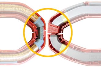
Photographs of a fluted valve plug and its matching seat are shown here as evidence of flashing and cavitation damage, respectively:

The plug of this valve has been severely worn by flashing and cavitation. The flashing damage is responsible for the relatively smooth wear areas seen on the plug.
Cavitation damage is most prominent inside the seat, where almost all the damage is in the form of pitting. The mouth of the seat exhibits smooth wear caused by flashing, but deeper inside you can see the pock-marked surface characteristic of cavitation, where liquid microjets literally blasted away pieces of metal.
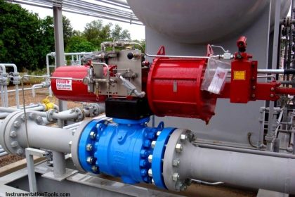
This trim set belongs to a Fisher Micro-Flat Cavitation valve, designed with process liquid flow passing down instead of up (i.e. first past the wide body of the plug and then down through the seat, rather than first up through the seat and then past the wide body of the plug).
This trim design does not prevent cavitation (as clearly evidenced by the photos), but it does “move” the area of cavitation damage down below the seat’s sealing surface into a long tube extending below the seat.
Although the ravages of flashing clearly took their toll on this valve’s trim, the valve would have been rendered inoperable much sooner had cavitation been at work along the plug’s length and at the sealing area where the plug contacts the seat.
The sound made by substantial liquid cavitation also contrasts starkly against the sound made by flashing. Whereas flashing sounds as though sand were flowing through the valve, cavitation produces a much louder “crackling” sound comprised of distinct impact pulses, reminiscent of what gravel or rocks might sound like if they were somehow forced to flow through the valve.
Sustained cavitation also has the detrimental effect of accelerating corrosion in certain process services. Bare metal surfaces are highly reactive with many chemical fluids, but become more resistant to further attack when a thin layer of reacted metal on the surface (the so-called passivation layer ) acts as a sort of chemical barrier.
Rust on steel, or the powdery-white oxide of aluminum are good examples: the initially bare metal surfaces react with their surrounding environment to form a protective outer layer, impeding further degradation of the metal beneath that layer.
Cavitation works to blast away any protective layer that might otherwise accumulate, allowing corrosion to work at full speed until the entire thickness of the metal is corroded through. The complementary destructive actions of cavitation and corrosion together is sometimes referred to as cavitation corrosion.
Several methods exist for abating cavitation in control valves:
- Prevent flashing in the first place
- Cushion with introduced gas
- Sustain the flashing action (i.e. delay cavitation)
Cavitation abatement method #1
This is quite simple to understand: if we prevent flashing from ever happening in a control valve, cavitation cannot follow. The key to doing this is making sure the vena contracta pressure never falls below the vapor pressure for the liquid. Several techniques exist for doing this:
- Select a control valve type having less pressure recovery (i.e. greater FL value)
- Increase both upstream and downstream pressures by relocating the valve to a higher-pressure location in the process.
- Use multiple control valves in series to reduce the lowest pressure at either one
- Decrease the liquid’s temperature (this decreases vapor pressure)
- Use cavitation-control valve trim
The last suggestion in this list deserves further exploration. Valve trim may be specially designed for cavitation abatement by providing multiple stages of pressure drop for the fluid as it passes through the trim.
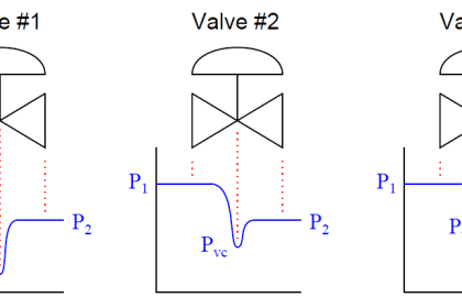
The following is a pressure versus location graph for a cavitating control valve. The liquid’s vapor pressure is shown here as a dashed line marked Pvapor:

A valve equipped with cavitation-control trim will have a different pressure profile, with multiple vena contracta points where the fluid passes through a series of constrictions within the trim itself:

This way, the same final permanent pressure drop (P1 −P2) may be achieved without the lowest pressure ever falling below the liquid’s vapor pressure limit.
An example of cavitation-control design applied to cage-guided globe valve trim is shown in the following illustration:

Ball-style control valves, with their relatively high pressure recovery (low pressure recovery factor FL values) are more prone to cavitation than globe valves, all other factors being equal.
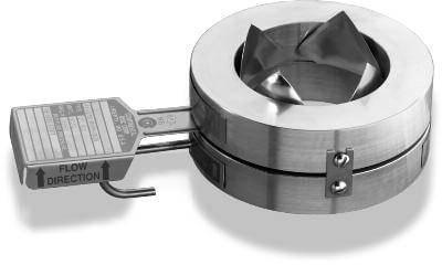
Special ball trim designed to help distribute pressure drops over a longer flow path is available, an example of this shown in the next photograph:

The round (ball-shaped) portion of the trim is on the far side of this piece, with the cavitation controlling structure visible in the foreground.
Fluid flow passing through the gap between the ball’s edge and the valve seat spills into this multi-chambered structure where turbulence helps develop pressure drops at several locations.
In a normal ball valve, there is only one location for any substantial pressure drop to develop, and that is at the narrow gap between the ball’s edge and the seat.
Here, multiple regions of pressure drop exist, with the intent of avoiding the liquid’s vapor pressure limit at any one location, thus eliminating flashing and consequently eliminating cavitation.
Cavitation abatement method #2
This is practical only in some process applications, where a non-reacting gas may be injected into the liquid stream to provide some “cushioning” within the cavitating region.
The presence of non-condensible gas bubbles in the liquid stream disturbs the microjets’ pathways, helping to dissipate their energy before striking the valve body walls.
Cavitation abatement method #3
This involves a strategy opposite that of method #1. If, for whatever reason, we cannot avoid falling below the vapor pressure of the liquid as the flow stream moves through the valve.
we may have the option of ensuring the downstream liquid pressure never rises above the liquid’s vapor pressure, at least until the fluid clears past the valuable control valve and into an area of the system where cavitation damage will not be so expensive.
This avoids cavitation at the cost of guaranteed flashing within the control valve, which is generally not as destructive as cavitation.
A pressure diagram shows how this method works:

Of course, flashing is not good for a control valve either. Not only does it damage the valve over time, but it also causes problems with flow capacity, as we will explore next.