This article discusses the automatic complex car parking system using the XG-5000 LS Electric PLC program using sensors. This car parking system has 2 gates, Gate-1 to enter the parking area and Gate-2 to exit the parking area. When a car enters the parking area, Gate-1 will Open and will Close when the car has passed the gate. If within 10 seconds after the gate Opens no cars enter, the gate will automatically Close.
When a car leaves the parking area, Gate 2 will Open and Close when the car has passed the gate. If within 10 seconds after the gate Opens no cars come out, the gate will automatically Close.
The number of cars in the Car Parking area will be counted.
Complex Car Parking Logic
In this program, the Buttons used are as follows:
- The START (P00000) button is used to turn ON the system.
- The STOP (P00001) button is used to turn OFF the system.
- The RESET_COUNTER (0.02) button is used to Reset the Counter data to zero “0”.
CAR IN
When the SENS_CAR_IN1 (P00003) sensor is Active because it detects an incoming car, the Gate IN will Open and the Output Gate GATE_IN_UP (P00040) will become ON. Gate IN will Stop moving to Open when Limit Switch LS_GATE_IN_UP (P00007) is Active.
When the SENS_CAR_IN2 (P00004) sensor is Active because it detects a car has entered, Gate IN will Close and the Gate Output GATE_IN_DOWN (P00041) will become ON. Gate IN will Stop moving Close when Limit Switch LS_GATE_IN_DOWN (P00008) is Active. Next, the Counter data in the memory word CAR_COUNTER (D00000) increases (+1).
If after Gate IN Opens and within 10 seconds no cars enter the parking area, then Gate IN will Close and the Output GATE_IN_ALARM (P00044) will be ON for a moment.
CAR OUT
When the SENS_CAR_ OUT1 (P00005) sensor is Active because it detects a car coming out, the Gate OUT will Open and the Output Gate GATE_OUT_UP (P00042) will become ON. Gate OUT will Stop moving to Open when Limit Switch LS_GATE_OUT_UP (P00009) is Active.
When the SENS_CAR_OUT2 (P00006) sensor is Active because it detects that a car has entered, the Gate OUT will Close and the Output Gate GATE_OUT_DOWN (P00043) will become ON. Gate OUT will Stop moving Close when Limit Switch LS_GATE_OUT_DOWN (P0000A) is Active. Next, the Counter data in the memory word CAR_COUNTER (D00000) is reduced (-1).
If after Gate OUT Opens and within 10 seconds no cars leave the parking area, then Gate OUT will Close and the GATE_OUT_ALARM (P00045) output will be ON for a moment.
Addressing Details
| Comment | Input (I) | Output (Q) | Word Memory | Memory Bits | Timers |
| START | P00000 | ||||
| STOP | P00001 | ||||
| RESET_COUNTER | P00002 | ||||
| SENS_CAR_IN1 | P00003 | ||||
| SENS_CAR_IN2 | P00004 | ||||
| SENS_CAR_OUT1 | P00005 | ||||
| SENS_CAR_OUT2 | P00006 | ||||
| LS_GATE_IN_UP | P00007 | ||||
| LS_GATE_IN_DOWN | P00008 | ||||
| LS_GATE_OUT_UP | P00009 | ||||
| LS_GATE_OUT_DOWN | P0000A | ||||
| GATE_IN_UP | P00040 | ||||
| GATE_IN_DOWN | P00041 | ||||
| GATE_OUT_UP | P00042 | ||||
| GATE_OUT_DOWN | P00043 | ||||
| GATE_IN_ALARM | P00044 | ||||
| GATE_OUT_ALARM | P00045 | ||||
| TIMER_IN_ALARM | T0000 | ||||
| TIMER_OUT_ALARM | T0001 | ||||
| SYSTEM_ON | M00000 | ||||
| CAR_COUNTER | D00000 |
XG5000 LS Electric PLC Programming
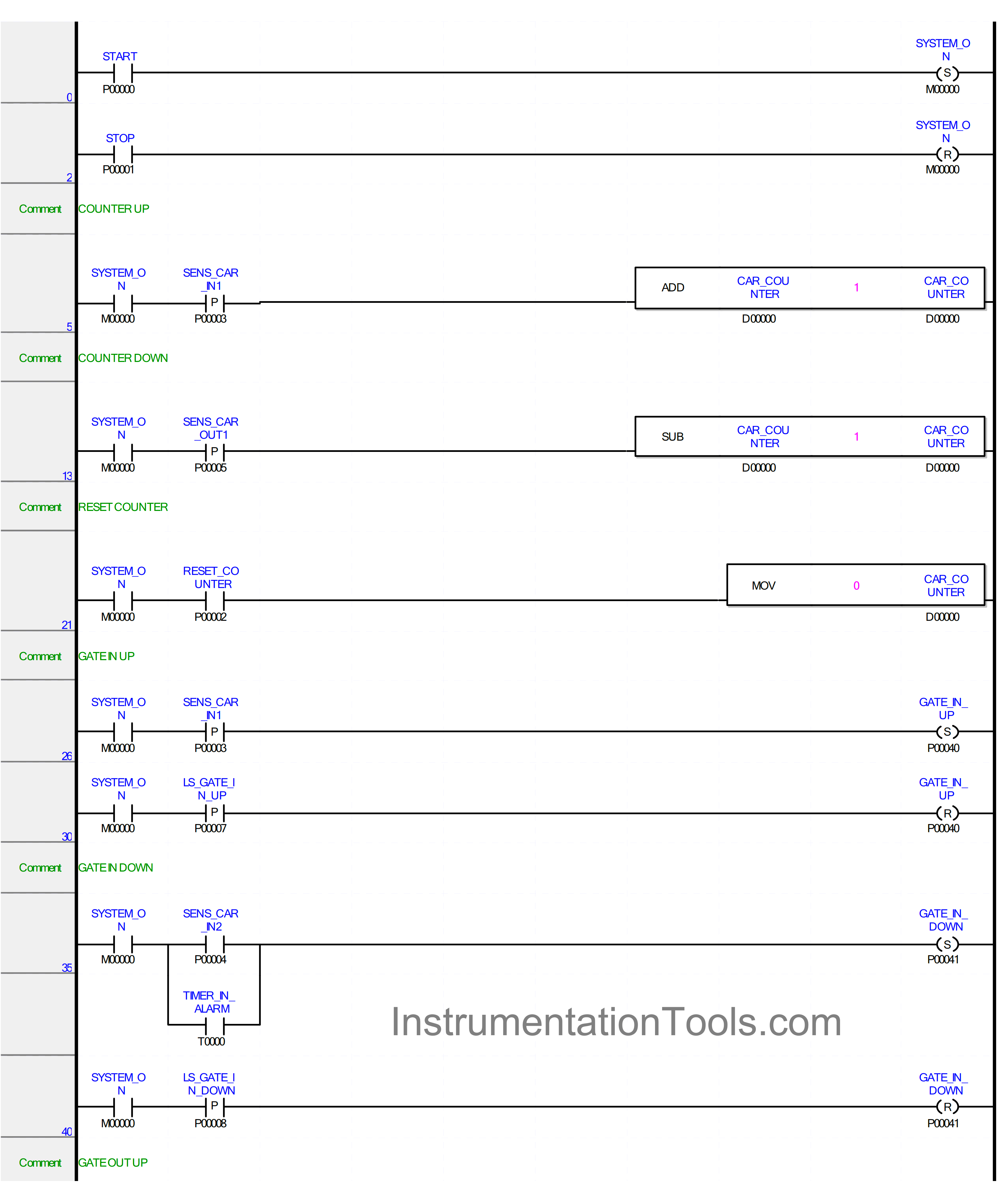
RUNG 0
In this Rung, the memory bit SYSTEM_ON (M00000) changes to the HIGH state if the START (P00000) button is Pressed. Because it uses the SET Coil Instruction, the memory bit SYSTEM_ON (M00000) will remain in the HIGH state even though the START (P00000) button has been Released.
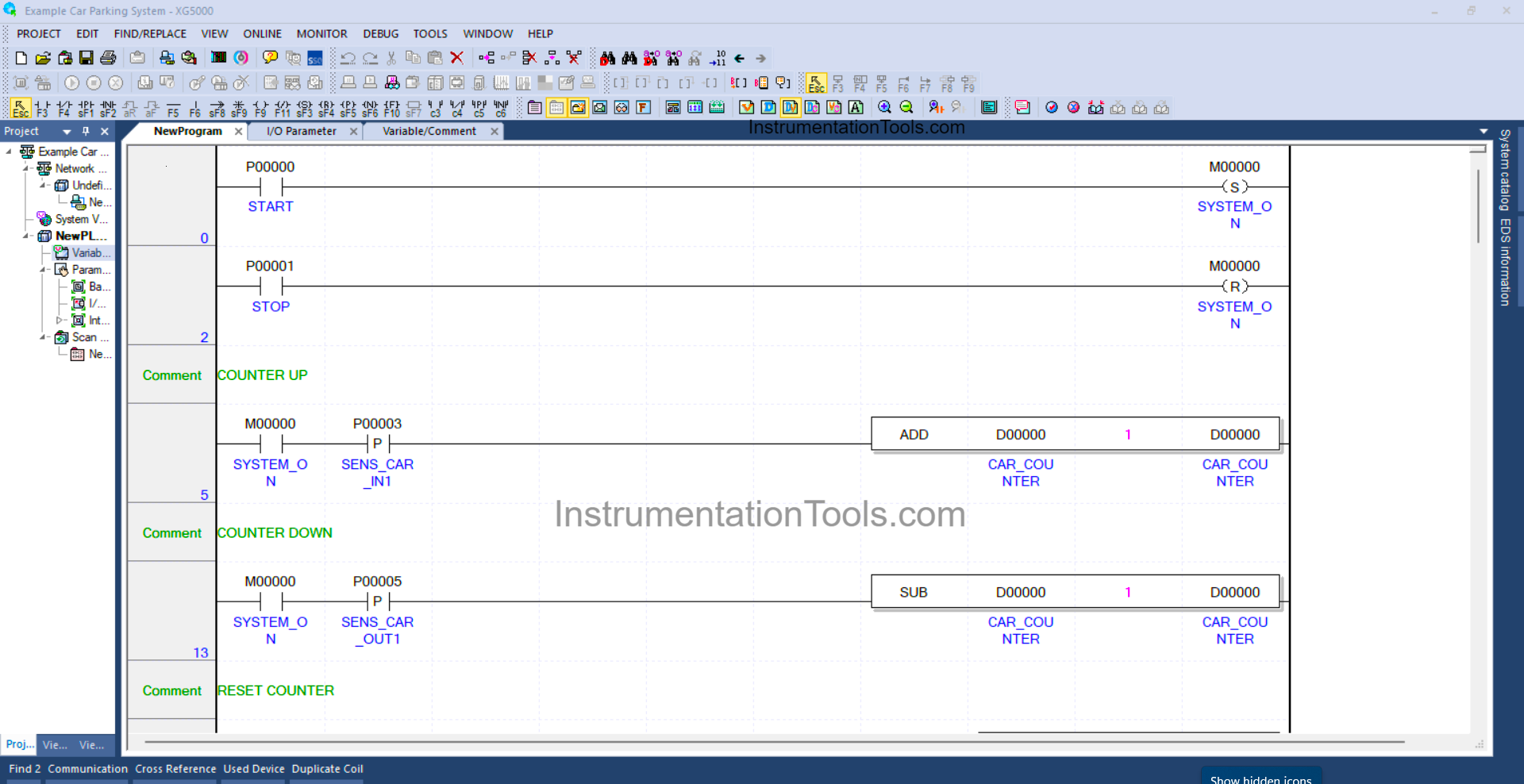
RUNG 1
In this Rung, the memory bit SYSTEM_ON (M00000) will be in the LOW state if the STOP (P00001) button is Pressed because it uses the RESET Coil Instruction.
RUNG 5
In this Rung, if the NO contact of the bit memory SYSTEM_ON (M00000) and Sensor SENS_CAR_IN1 (P00003) in the HIGH state, then the value in memory word CAR_COUNTER (D00000) will increase (+1).
The ADD instruction will add a value (+1) to the memory word CAR_COUNTER (D00000) each time it is Activated.
RUNG 13
In this Rung, if the NO contact of the bit memory SYSTEM_ON (M00000) and Sensor SENS_CAR_OUT1 (P00005) in the HIGH state, then the value in memory word CAR_COUNTER (D00000) will decrease (-1).
The SUB instruction will subtract the value (-1) from the memory word CAR_COUNTER (D00000) each time it is Activated.
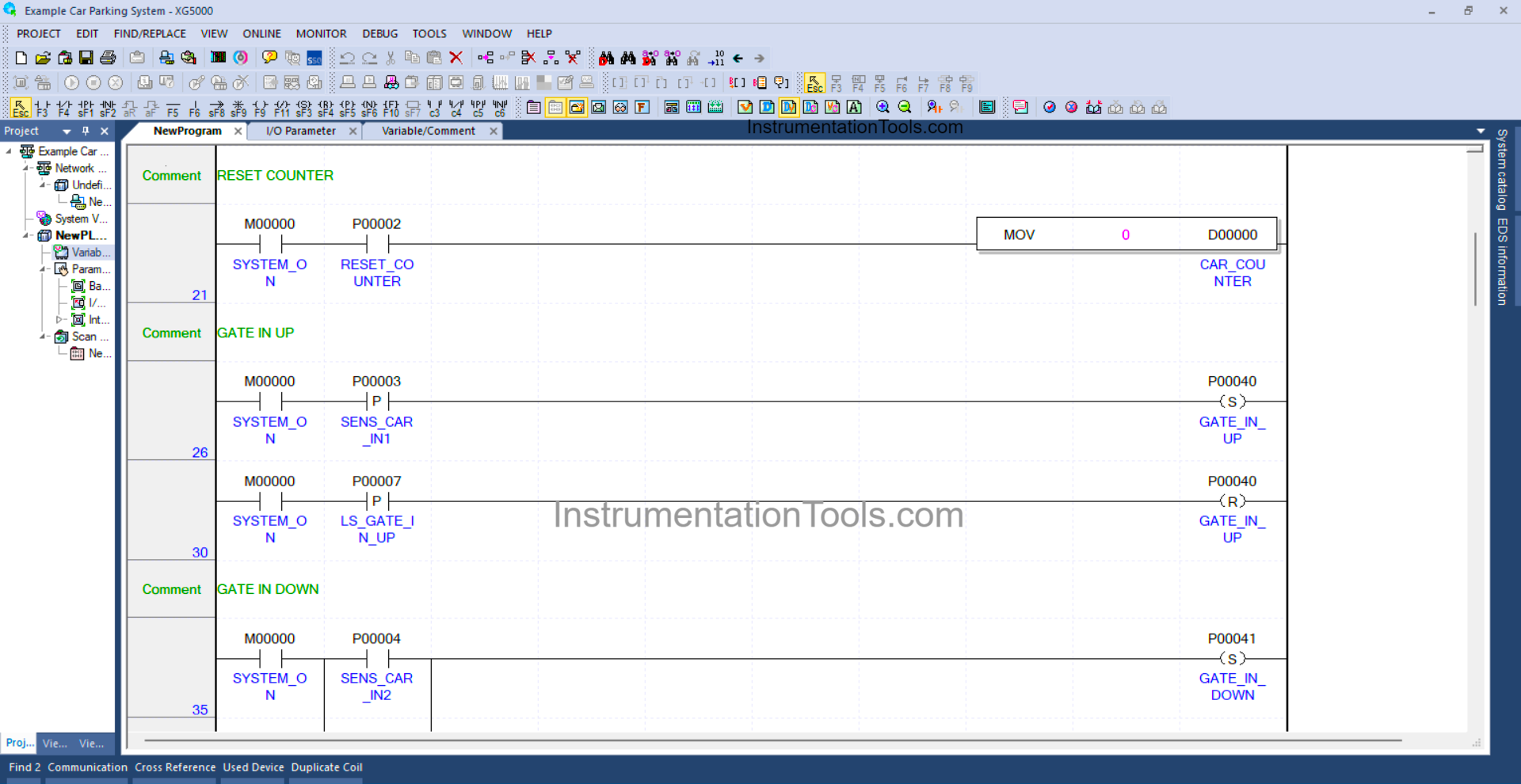
RUNG 21
In this Rung, if the NO contact of the memory bit SYSTEM_ON (M00000) in the HIGH state and the RESET_COUNTER (P00002) button is Pressed, then the value in the memory word CAR_COUNTER (D00000) will be Reset to zero “0”.
RUNG 26
When the NO contact of the memory bit SYSTEM_ON (M00000) and the SENS_CAR_IN1 (P00003) Sensor is in the HIGH state, the GATE_IN_UP (P00040) Output will be in the HIGH state.
Because it uses the SET Coil Instruction, the GATE_IN_UP (P00040) Output will remain in the HIGH state even though the SENS_CAR_IN1 (P00003) Sensor has become in the LOW state.
RUNG 30
Because it uses the RESET Coil Instruction, if the NO contact of memory bit SYSTEM_ON (M00000) and the Limit Switch LS_GATE_IN_UP (P00007) in the HIGH state, then the GATE_IN_UP (P00040) Output will be in the LOW state.
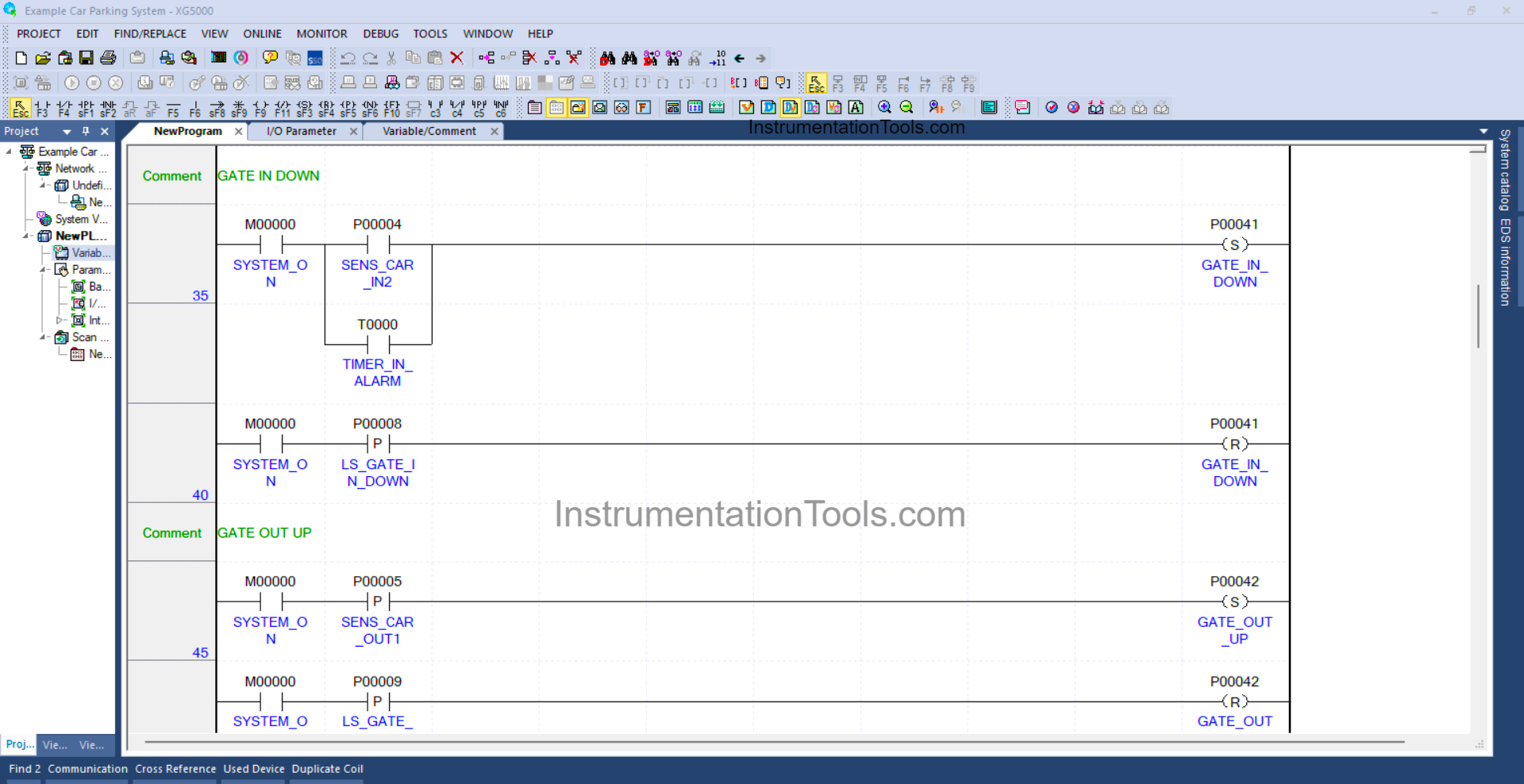
RUNG 35
In this Rung, when the NO contact of memory bit SYSTEM_ON (M00000) and the SENS_CAR_IN2 (P00004) Sensor is in the HIGH state, then the GATE_IN_DOWN (P00041) Output will be in the HIGH state.
Or if the NO contact of Timer TIMER_IN_ALARM(T0000) is in the HIGH state, then the GATE_IN_DOWN (P00041) Output will be in the HIGH state.
Because it uses the SET Coil Instruction, the GATE_IN_DOWN (P00041) Output will remain in the HIGH state even though the NO contact of the SENS_CAR_IN2 (P00004) Sensor or TIMER_IN_ALARM (T0000) Timer in the LOW state.
RUNG 40
Because it uses the RESET Coil Instruction, if the NO contact of memory bit SYSTEM_ON (M00000) and the Limit Switch LS_GATE_IN_DOWN (P00008) are in the HIGH state, then the GATE_IN_DOWN (P00041) Output will be in the LOW state.
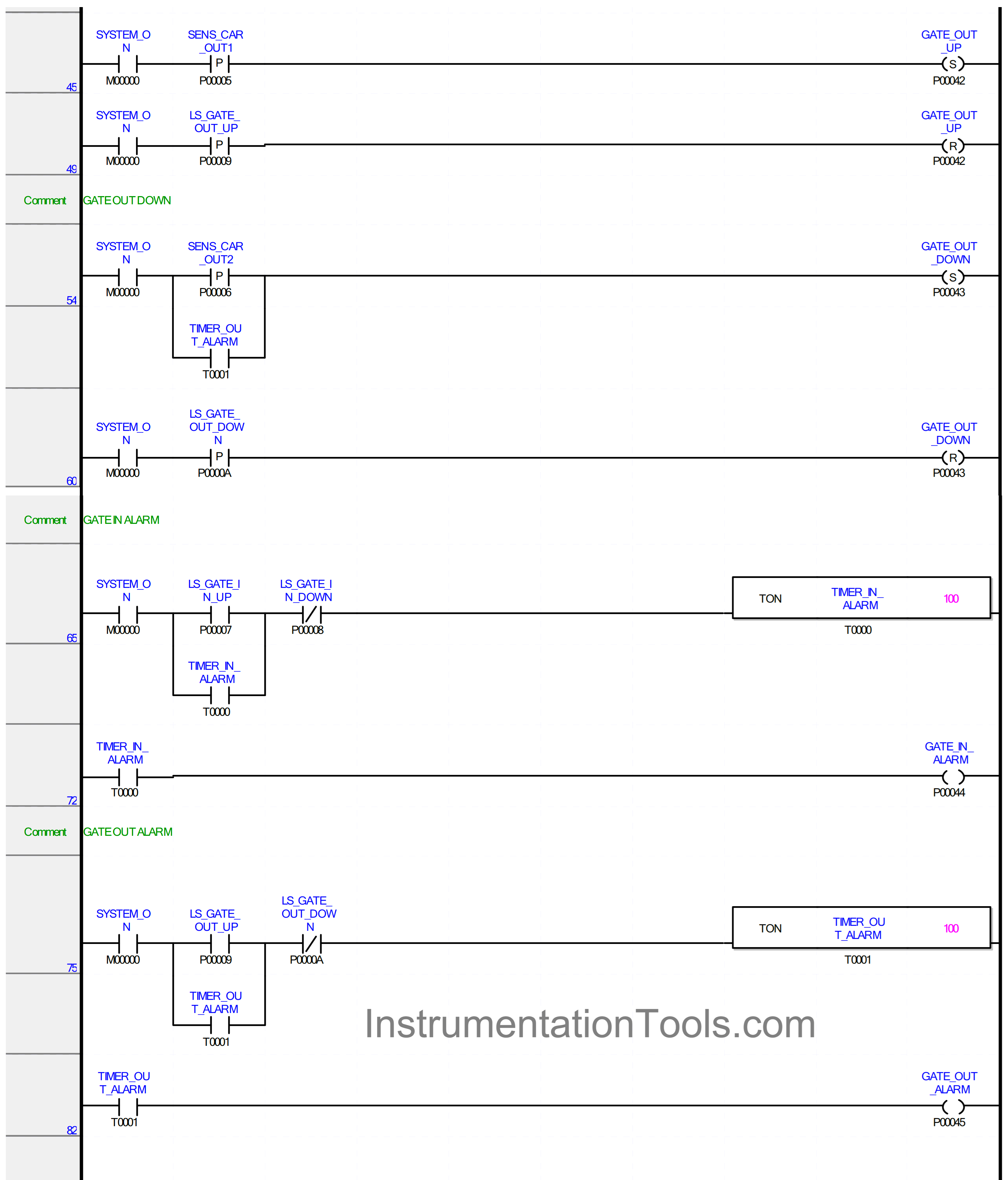
RUNG 45
When the NO contact of memory bit SYSTEM_ON (M00000) and the SENS_CAR_OUT1 (P00005) Sensor is in the HIGH state, the GATE_OUT_UP (P00042) Output will be in the HIGH state.
Because it uses the SET Coil Instruction, the GATE_OUT_UP (P00042) Output will remain in the HIGH state even though the SENS_CAR_OUT1 (P00005) Sensor has become in the LOW state.
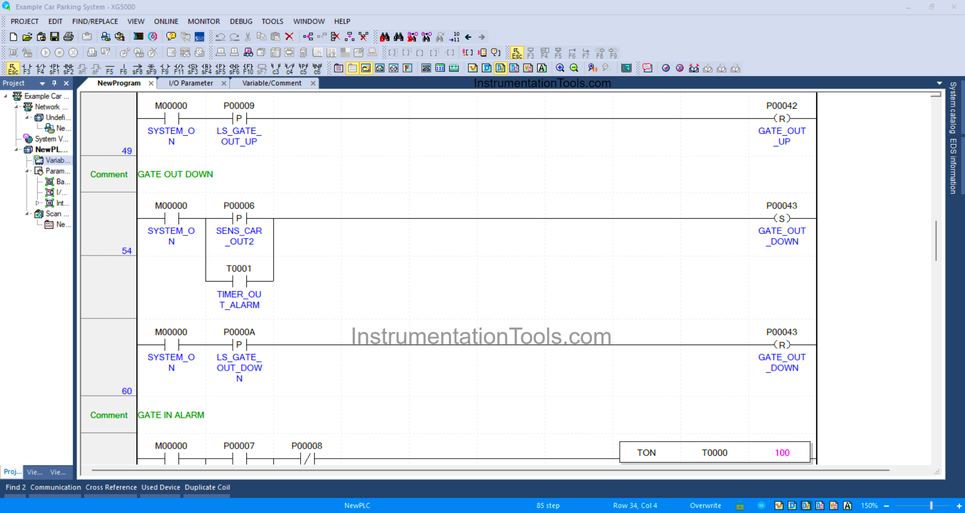
RUNG 49
Because it uses the RESET Coil Instruction, if the NO contact of memory bit SYSTEM_ON (M00000) and the Limit Switch LS_GATE_OUT_UP (P00009) in the HIGH state, then the GATE_OUT_UP (P00043) Output will be in the LOW state.
RUNG 54
In this Rung, when the NO contact of memory bit SYSTEM_ON (M00000) and the SENS_CAR_OUT2 (P00006) Sensor is in the HIGH state, then the GATE_OUT_DOWN (P00043) Output will be in the HIGH state.
Or if the NO contact of TIMER_OUT_ALARM (T0001) Timer is in the HIGH state, then the GATE_OUT_DOWN (P00043) Output will be in the HIGH state.
Because it uses the SET Coil Instruction, the GATE_OUT_DOWN (P00043) Output will remain in the HIGH state even though the NO contact of SENS_CAR_OUT2 (P00006) Sensor or TIMER_OUT_ALARM (T0001) Timer in the LOW state.
RUNG 60
Because it uses the RESET Coil Instruction, if the NO contact of memory bit SYSTEM_ON (M00000) and the Limit Switch LS_GATE_OUT_DOWN (P0000A) in the HIGH state, then the GATE_OUT_DOWN (P00043) Output will be in the LOW state.
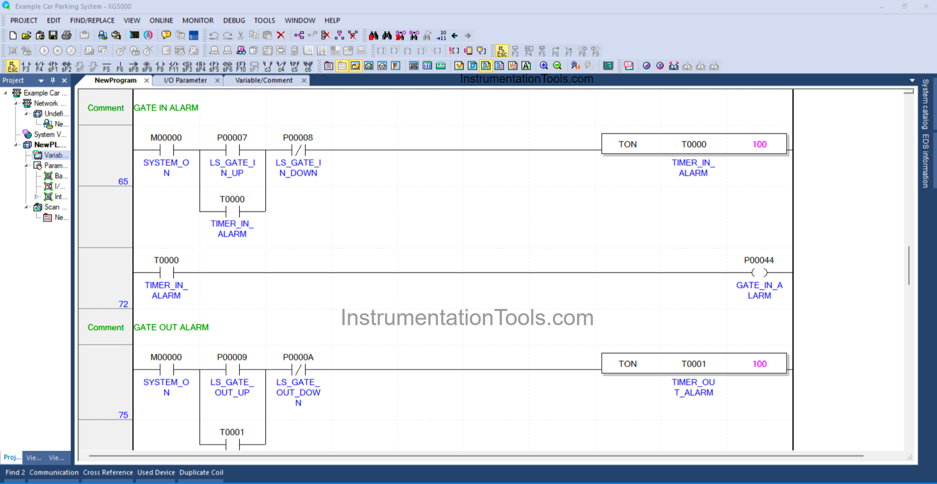
RUNG 65
In this Rung, when the NO contact of memory bit SYSTEM_ON (M00000) and the Limit Switch LS_GATE_IN_UP (P00007) are in the HIGH state, the TIMER_IN_ALARM (T0000) Timer will start counting up to 10 seconds.
After the Timer TIMER_IN_ALARM (T0000) has finished counting the Latching contact will be Active. The TIMER_IN_ALARM (T0000) timer will be OFF if the NC contact of Limit Switch LS_GATE_IN_DOWN (P00008) is in the HIGH state.
RUNG 72
In this Rung, when the NO contact of TIMER_IN_ALARM (T0000) Timer in the HIGH state, the GATE_IN_ALARM (P00044) Output will be ON.
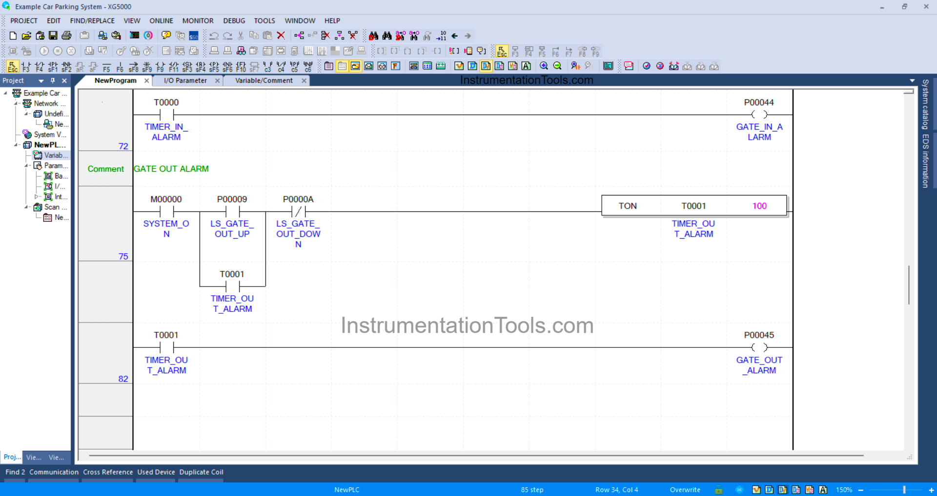
RUNG 75
In this Rung, when the NO contact of memory bit SYSTEM_ON (M00000) and the Limit Switch LS_GATE_IN_UP (P00007) are in the HIGH state, the TIMER_OUT_ALARM (T0001) Timer will start counting up to 10 seconds.
After the Timer TIMER_OUT_ALARM (T0001) has finished counting the Latching contact will be Active. The TIMER_OUT_ALARM (T0001) timer will be OFF if the NC contact of the Limit Switch LS_GATE_OUT_DOWN (P0000A) is in the HIGH state.
RUNG 72
In this Rung, when the NO contact of the TIMER_OUT_ALARM (T0001) Timer is in the HIGH state, the GATE_OUT_ALARM (P00045) Output will be ON.
Read Next:
- PLC Logic Train Detection and Gate Operation
- Weighing with Labeling PLC Automation Logic
- Functional Block Diagram Analog Alarm Logic
- Timer-Based Sequential PLC Programming
- PLC Programming for Baking with Auto Mode